| Crane #1 |
| I've called this invention crane #1 simply because i like making cranes, so there will no doubt be crane #2 etc. in the future. also coz i couldn't think of anything else. The crane uses: 3 motors Pneumatics set Assorted pieces from all sets |
| Ok, i made this invention primarily to test out the turntable part i got in the builder's set. It is made up of basically 3 modules. The Pneumatic Module: This module (or mechanism) controls the pneumatic system used in the crane. I've used the pneumatics to lower and raise the crane arm. The module works by having the motor pump air into either end of the piston, depending on which way the motor spins i.e. spin the motor one, it pumps air into the top of the piston, and lowers the arm, spin the motor the other way, pumps into the bottom of the piston, and raises the arm. The Turntable module: The turntable module is responsible for spinning the turntable piece around. the whole crane arm and winch module is attached to the turn table. This module is pretty much a motor driving a worm gear box, which, through a series of gears, meshes with, and turns, the turntable. The Winch Module: The winch module winds the cable (string) in and out. It uses a motor to drive a worm gear box and the string is just attached to the output axle of the box. Spin the motor one way, winds the string up, spin the motor the other way, winds the string out. Ok here are the pictures, with explanations. (click on the pics for larger view, but they'll take a minute to download, i couldn't get them any smaller) |
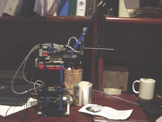 |
| Here is a picture of the crane over all. As you can see, it's pretty simple. You can see the 3 modules quite clearly, and the arm is in the upper position. |
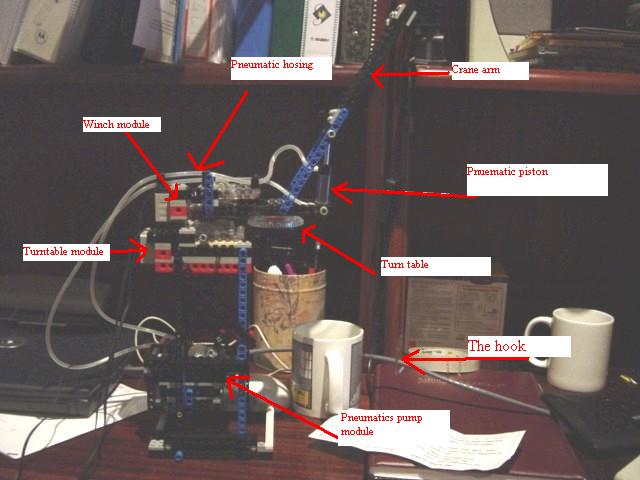 |
| Here is the same pic as above, but with labels on it.Here you can see where the 3 modules are located. Everything above the turntable turns around. This works ok, but as you can see, it is limited by the pneumatic lines and motor cables. |
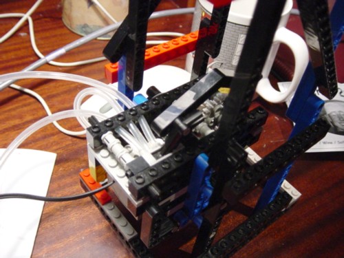 |
| This is the close-up of the pneumatics module. You can't really see much. The three hoses are attached to the switch. The middle hose comes from the pump(which is on the side of the module which is out of view), and the two outside hoses go to the either end of the piston. You can also see where the motor is by the motor cable coming out of the back. |
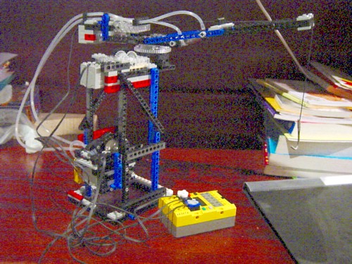 |
| This is a picture with the arm down, and also shows how the top turns. Also, the yellow thing that the wires plug into is the RCX. It is pretty much the brains of whole thing. It controls the motor outputs, sensor inputs, can be programmed etc. It's an awesome little dealy. (i know the pics shit house quality, but the photo i took was really dark, and this still gives a pretty good idea). |
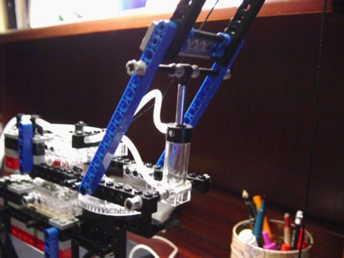 |
| This is a picture of the pneumatic piston. As you can see, it is attached like a brace between the arm, and winch module. You can see where the air is pumped into either end of the piston. Pumping air into the top would cause the piston to draw in, and pull the arm down. Pumping air into the bottom pushes out the piston, and pushes up the arm. You can also tell, i built it very quickly, and very roughly. (it doesn't actually work that well, but still does the job) |
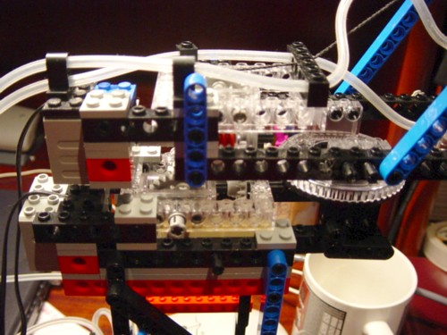 |
| This is a close up of the winch and turntable modules. You can see the two motors (the two grey blocks at the back with the wires comin out of them), the turntable piece, and whatever else you can find. |
| Ok, that is it for Crane #1, if you have any other questions about how it works, feel free to email me your questions |