741/2C ~ Ser. No. 781212

January 2006 ~ Indianapolis, Indiana
Mike Robbins ~ Tech Article #1
| Home |
Tech Pages |
356 Registry |
 |
1. This is measuring how much the bearing for the pinion shaft protrudes from the surface of the intermediate plate. The measurement here is 0.323". |
 |
2. This is measuring the depth of the recess in the cover plate for the above bearing. The cover actually goes over the main shaft bearing, too; but we are only concerned with the pinion shaft bearing. The reading here is 0.314”. This dimension is subtracted from the dimension in [1] giving 0.009”. From that we subtract 0.003” which is the preload [amount of squeeze] on the bearing. We now have 0.006” which is the thickness of gasket to put between the cover and the intermediate plate to give the correct preload. A variation of +/- 0.002” is allowed here; so I installed the closest I had available, which was 0.005” thick. |
 |
3. Here is where I should have shown the separate shaft assemblies. This shows the main shaft and pinion shaft in tool no. P-55. I'm adjusting the height of the main shaft so that it is properly aligned with the pinion shaft. To do this, I'm turning a threaded collar that supports the main shaft. |
 |
4. This shows me tapping the main shaft bearing in the intermediate plate with an appropriately sized piece of pipe to get it started on the main shaft. |
 |
5. Now we have the assembly in the hydraulic press to press the assembly together. |
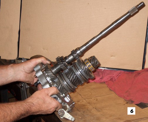 |
6. Here is the assembly after being pressed together. |
 |
7. The shift rods, shift forks and detents have been assembled loosely to the cluster. It is time to adjust the shift forks, tighten their pinch bolts and tighten the detent plugs. I use blue Loctite on the threads of the detent plugs and tighten them to 18 ft lbs. The next step is to rotate the shift rods so that their heads are parallel and equally spaced. The camera should have been a little lower to look straight into the heads of the shift rods. |
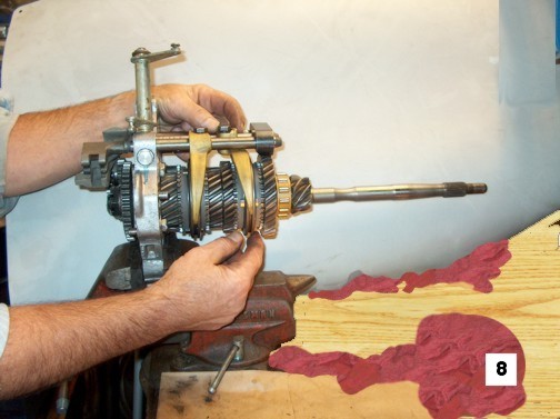 |
8. The important goal here is to have the operating sleeve centered between the two gears. About 1 1/2" above the fingers on my right hand you can see the shiny ends of the spider that positions the operating sleeve. There is more showing on the left than on the right so the sleeve has to be adjusted slightly to the left.  |
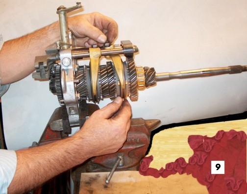 |
9. Here we see the operating sleeve centered between the ends of the spider and consequently, centered between the gears. The pinch bolt, seen between the fingers on my left hand, holds the fork to the shift rod can now be tightened. I use blue Loctite and torque them to 23 ft lbs. This is tighter than the factory specifies but we don't want them to come loose. I've never stripped the threads in the bronze shift forks. |
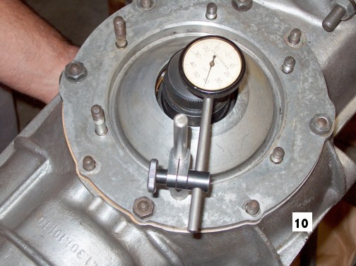 |
10. The mandrel that is part of tool P-33 is inside the case and is a sliding fit in the bearings in the side covers. The mandrel has shoulders that abut the side bearings and the length of the tool from shoulder to shoulder is stamped on the tool. My mandrel is 5.594". In the photo the mandrel is resting on the right side bearing, as the trans case is rotated 90 degrees from its normal position. The mandrel is pushed upward to contact the left side bearing and the travel distance is measured with the dial indicator. In this case 0.140". [The dial indicator has made one and a fraction revolutions.] Adding the 0.140" to the 5.594'' length of the mandrel gives 5.734 as the total space between the side bearings. |
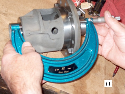 |
11. The width of the differential between the side bearing contact surfaces is measured. In this case it is 5.432". Subtracting this dimension from the space determined above gives the total thickness of the left and right side shims to fill the space. Actually, 0.006" is added to this to give the correct preload for the side bearings. In this case that gives a total thickness for the two shims at 0.308". Additional work is required to determine the split of the total thickness into the left and right shims to give the correct backlash of the ring gear and the teeth on the pinion shaft. The total thickness of the two shims must remain at the 0.308" -0.310" [There is a tolerance of +0.002"]. Thus, if one shim is made 0.003" thicker, the other must be made 0.003" - 0.005" thinner. |
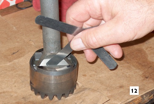 |
12. Here we are measuring the clearance between the fulcrum plates, often referred to as "trunnion blocks", and the inner end of the axle as the parts are assembled into the differential side gear. This is done with both axles and their respective side gears and fulcrum plates. The wear limit for this clearance is 0.010”. Yours were less than this but I like to get them back to the tolerance for new parts, which is 0.002” – 0.006”. By using new fulcrum plates we were able to get 0.004” and 0.0025”. |
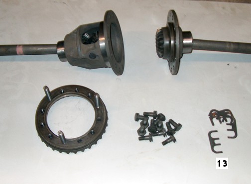 |
13. This is supposed to illustrate the parts of the differential-axle assembly. Unfortunately, we neglected to include the spider gears, the shaft for the spider gears and the pin for retaining the shaft in the housing. In this pic these parts, along with the axles, have been already assembled into the differential housing and differential cover. The small parts in the center are the ring gear bolts and their lock plates. Note the 3 studs screwed into the ring gear. These are used as an aid in aligning the bolt holes in the differential housing flange and the differential cover. |
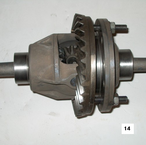 |
14. Here the differential assembly is being drawn together by tightening nuts on the 3 studs in the ring gear. Once the parts are drawn tightly together the ring gear bolts are assembled and the studs removed. [The studs have a slot in the ends so a screwdriver can be used to remove them.] I use blue Loctite on the bolts and torque them in stages to 58 ft lbs and then assemble the lock plates. One lock plate fits in grooves in two adjacent bolt heads. The “arms” of the “U” shapes in the lock plates are squeezed together and then the outer edges are bent up against the flats on the bolt head. There is very little clearance inside the transmission case for the edges of the lock plates so it is necessary to go around each one with a hammer and tap any protruding portion inward. |
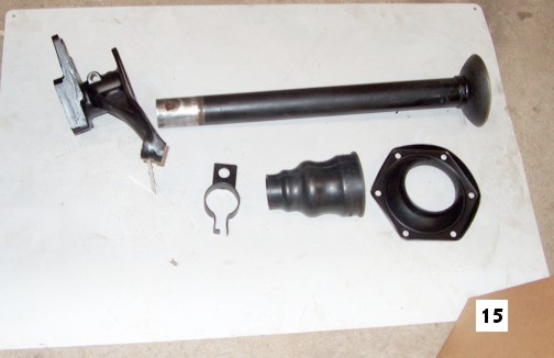 [1] I usually have to have the parts stripped of old paint and different blasting media is used on the casting than on the other parts. [2] The bell end of the axle tube may be deformed slightly and thus require excessive gaskets under the cover plate to give freedom of rotation against the spherical surface of the aluminum side cover on the trans case. If the customer’s tube requires excessive gaskets, I will use a tube from my supply, sometimes checking two or three to find one with optimum fit. [3] the cover plate may be distorted and not provide a flat surface for the gasket[s] and sealant. I attempt to flatten distorted plates but sometimes can’t get them flat enough. In those cases I change to another cover plate from my supply. This is the toughest place on the trans to prevent leaks. [4] It is much easier to assemble the new solid boot. Some people stretch them over the bell end of the axle tube but sometimes tear them in the process. |
15. In the upper part of this pic is the bearing housing and axle tube. The lower shows the brake line clamp, solid boot and the cover plate. Many people do not disassemble the axle tube but I do it for four reasons listed below the photo. |
 |
16. This is a V W tool for supporting the axle tube when pressing the bearing housing onto the tube. It is improper to press the housing onto the tube by merely placing the bell end of the tube on a press plate. That tends to distort the bell of the tube and resulting in the problem mentioned 1n 15 above. Note that the tool supports the actual end of the tube and not the bell. |
| Page
last updated 1.28.2006 Top |
|