Happy New Year.
17/03/08
We saw a charming old video from Imperial with an old guy demonstrating induction motors and coil guns and the like.
You already had the PHY5 papers I was going to give you except the spec. Never mind.
Rail guns, also the difference between them and coil guns.
We built transformers and they worked rather nicely.
Most of the stuff you need to know about them is GCSE.
We discussed transformers and their use in the national grid.
![]()
They have 2 coils joined by a (laminated to avoid eddy currents) iron core. AC (alternating current) sent into the primary coil causes an alternating voltage to be induced in the secondary coil. This is due to the changing magnetic field putting a force on the electrons in the second coil.
The alternating voltage can be larger or smaller than the input voltage depending on whther there are more or less turns in the secondary coil than the primary one.
We looked at a little mock up of the power distribution system.
![]()
Power is generated by turning coils in magnetic fields. It is then stepped up to very high voltages to be sent long distances around the country.
In a nutshell, you must learn the following points:
N1/N2=V1/V2
A single long straight conductor passing perpendicularly through a magnetic field will move a distance v in one second. (d=st).
The area swept out by the wire per second is therefore lv. The magnetic field is constant, so the voltage across the wire can be calculated:
emf = Blv
We started on the huge set of questions on induction that I had the presence of mind to steal. More on them next time.
I cut myself on the generator and it really hurt. Damnit. Extra sessions for retakers will be on Wednesday afternoons. For some reason PHY4 was awful all round.
More on electromagnetic induction. We saw an example of a motor/generator. Put a voltage in and you get movement out. Put movement in and you get an induced voltage out. The induced voltage is often referred to as an emf (electromotive force.)
Any relative movement between a conductor and a magnetic field will induced a voltage. An increased speed of movement, or an increased magnetic field will increase the induced voltage. Reversing the direction of the movement reverses the direction of the voltage induced.
In fact the size of the induced voltage can be calculated as the change in flux linkage.
"Linkage" means the area of the magnetic field that is affecting a conductor. So a change in the area affected or in the magnetic field will induce a voltage.
This can be done in a number of different ways as above.
We looked at various examples of Lenz's law, showing that any induced current caused by an induced emf due to a change in magnetic flux on a conductor will cause a magnetic field which acts to help stop the change which created it.
Of course, if the conductor has no resistance, the induced current will produce a magnetic field large enough to completely cancel the change that is causing it.
Hence, superconducting levitation.
Induction Caltech vid Part 2 and 3 link on to it.
We'll look at a very popular application of induced emf - transformers, next time.
Short lesson what with you guys running to get your results. Perhaps they weren't all that great though....
I talked about my general hatred of the term "magnetic flux" and why it is stupid.
I introduced electromagnetic induction just with a wire, magnet and an microammeter. It is precisely the same effect as causes all magnetic forces (magnetic force on a moving charged particle) but is just expressed differently.
We saw a demonstration of electromagnetic induction. We already know that moving charges experience a force in a magnetic field. If a conductor is physically moved through a magnetic field, the free charge carriers inside the conductor experience a force. This force pushes them through the conductor, it is an induced voltage. An induced voltage can cause an induced current if the conductor is connected as part of a complete circuit.
Both positive and negative charges within the wire feel a force (in opposite directions), but only the free electrons are able to move.
The induced voltage is reversed if the wire is moved the other way. The induced voltage is made stronger by moving the wire faster, or having a stronger magnetic field.
At this stage I was unable to avoid any longer speaking of magnetic flux which people seem to love even though it's a bit rubbish.
We looked at Hall probes.
They are explained in some detail here.
A current is passed through a wafer of semiconducting material. A microvoltmeter measures the size of the magnetic force on the moving charge carriers due to an external magnetic field perpendicular to the current. The microvoltmeter is position perpendicular to the flow of current and in no way measures the emf which causes the steady current to pass through the probe.
Hall probes must be calibrated so that the reading from the voltmeter can be converted into a magnetic field strength in Tesla.
We calibrated Hall probes, by sticking them in the middle of a solenoid with a known n (turns per m). We could work out the expected value of magnetic field using the solenoid formula (B=mu0nI). The current in the solenoid was varied to provide a varying magnetic field.
The Hall probes all reacted linearly to the change in magnetic field. You were able to measure a few more magnetic fields to try them out.
They weren't bad in that they agreed on the true magnetic field strength in my cool horseshoe magnet (more like 0.07 Tesla).
HW Do the Chapter 18 practise questions which make you use some of the formulae discussed last time. Beware "magnetic flux density" just means magnetic field strength.
I hate Mondays. They're rubbish.
We have to do Hall probes tomorrow. Today, formulae for magnetic fields within a solenoid and around a straight wire, the definition of the Amp (which is a base unit) and a conversation I had in Nando's on Saturday.
We looked into the theory behind the strength of magnetic fields produced by a solenoid, explained in excessive detail here.
The number of turns per m (n) , and the current (I) are the 2 variables which affect the strength of the field within the coil. mu0 is a fundamental constant, the magnetic permeability of free space.
I'm still troubled by that relativistic magnetic problem posed by Anthony. More thought required.
We performed an experiment to see how the force on an current carrying wire perpendicular to an external magnetic field varied with the current in it.
These are the results we got, showing that the force is clearly proportional to the current (I). It is also proportional to the size of the external magnetic field (B) and the length of wire inside the field (l).
From these 3 factors we get the equation for the force on a perpendicular current carrying wire in an external magnetic field:
Force = B * I * l
The above equation only works for the wire being totally perpendicular to the field, if it isn't you can resolve the current (it is a vector) into perpendicular and parallel components.
In fact, magnetic field strength is defined by the above equation, measured in Tesla (or N/Am). 1 Tesla would be a field sufficiently strong to produce a force of 1 Newton on 1m of wire with 1A flowing in it.
We didn't have a chance to start talking about Hall probes so we'll get into them next time.
I had calmed down a bit about my whole "magnetism as a reletivistic correction of electrostatic forces" rant last time. But still went into relativity a bit more. Here and here were a smidgen of help.
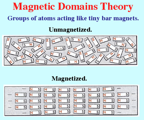
I just introduced the basic difficulty really which is that magnetism is not a "real" radial field like gravity and electrostatics but comes about due to moving charge. A magentic field is a region in space where a moving charge or permanent magnet will feel a magnetic force.
Permanent magnets only have a magnetic field due to the overall internal structure and movement of the charge which is held within them. ("Spin" a fundamental quantum property of particles is apparently largely responsible for the magnetic field, but personally I like to picture little electrons going in circles.)
Any how, you need to remember a few thing from GCSE about the shapes of magnetic fields.
Important points:
A current carrying wire experiences a force in an external magnetic field. The force is always at right angles to the direction of the current and the direction of the magnetic field lines.
The direction of the force can be determined by Fleming's left hand law.
The physical reason for this force is due to the combining of the magnetic field from the the wire and the external magnets. The fields agree on one side of the wire, but cancel each other out on the other. This is known as the catapult field effect.
A force is always felt from areas of strong magnetic field to areas of weak magnetic field. Strong fields are shown by the field lines being closer together.
The direction of the force will be reversed if either the current is reversed or the magnetic field is reversed (but not both). The force is made stronger by increasing the current (more moving charge to experience a force) or making the external magnetic field stronger.
We have seen that a straight current carrying wire has a magnetic field shaped in concentric rings. If the wire is curled around into a coil shape (a solenoid), the magnetic field produced when it carries current is shaped exactly like that of a bar magnet.
So a coil of wire is essentially a magnet that you can turn on and off by switching the electric current on and off. An electromagnet.
Electromagnets have a great many applications in many areas. They can be strengthened by adding a soft iron core to reinforce the magnetic field, or just by increasing the current flow.
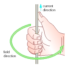
The North pole of the electromagnet can be found by using the right hand grip rule.

Right-Hand Grip Rule for solenoid
When the wire is coiled into a solenoid. Then you grips the solenoid by your right hand, so the fingers curl the same way of the current, the thumb points the north pole of the solenoid.
HW I'm sure I said something, but you'll have to remind me.
Last Friday afternoon I was beside myself with excitement when I discovered a reasonable way of describing that magnetism is actually just electrostatics but with relativistic effects taken into account.
It seemed more confusing and rather less exciting on a Monday morning.
It is, nevertheless, very exciting so look here.
Explanations above are probably better than mine.
Emergency over. Log graphs were covered. They may turn up in the practical exam if you have some results which look like an exponential decay.
A practical of sorts. You had an excuse to flick elastic bands around the place.
We looked at the analogy between the energy stored on a capacitor and the energy stored on a spring.
Energy used is the area under the graph of voltage against charge.

Energy stored = 1/2 VQ
Substituting in from C=Q/V can give you
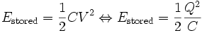

You plotted Energy stored vs. V2 and got a straight line through the origin with a gradient (roughly) equal to half the capacitance.
This is very similar indeed to the situation for the energy stored on a spring.
The above can be used to calculate the rate of energy lost moving at a constant speed against a constant frictional force for example.
The elastic energy stored in a spring can be calulated by finding the area under its force/extension graph.

If the spring obeys Hooke's law, F = kx
and Energy stored = 1/2Fx (area od triangle)
So energy stored = 1/2kx2
This only works for springs below their elastic limit.
Danger! Alarm bells etc. I forgot to teach you about one final thing on radioactive decay and capacitors.
How to plot a straight line graph of radioactive decay or capacitor discharge data by taking natural logs. We'll go through this too in the next single lesson.
The gradient above is -lambda and the intercept is lnNo
The above is what happens if you reverse the polarity of dielectric capacitors at a high enough voltage...
HW Still on those assessment questions. Lets do the chapter Qs in the next lesson.
Gravitational vs. Inertial mass
We finished off the analogy between radioactivity and capacitor discharge.
HW Look at ass qs 17-19.
Charging a capacitor at a constant current for a known time? Yes.
We then charged up some more capacitors, but this time through a variable resistor. We adjusted the variable resistor in such a way as the current stayed the same all the time.
The above graph shows the usual decrease in current over time. The total amount of charge which has flowed is equal to the average current multiplied by the time (Q=It) or the area under the graph. However, it is awkward to calculate the area under the graph without using integration. You may be expected to "count the squares", I hope not.
If, by changing the resistance gradually, the current is kept the same throughout the charging things are much easier.
Q = It, nice and simple.
The capacitor charging graph is exactly the same sort of shape as the graphs which show radioactive decay. Much more on this tomorrow.
We looked at the analogy between radioactive decay and discharging a capacitor.
The radioactivity of a sample of unstable nuclei is proportional to the number of nuclei present. The rate of change of number of nuclei is equal to the radioactivity. The gradient of an N/t curve is equal to the numerical y values in the second (A/t) at any time.
They all decay with the same basic shape. The rate of discharge in a capacitor is proportional to the amount of charge on it (and hence the voltage across it). The rate of loss of charge on the capacitor is equal to the current flowing at any stage. The gradient of the a Q/t curve is equal to the numerical y values in the second (I/t) at any time.
The mathematics of the 2 phenomena is almost identical.
N (number of nuclei) is analogous to Q (charge)
A (activity) is analogous to I (current)
Lambda (the decay constant) is analogous to 1/RC (inverse of the time constant for the circuit)
Each can be said to have a "half life", although the time constant (Resistance times Capacitance) tends to be used for capacitor discharge. It represents the time taken for the charge, voltage and current to drop to 1/e of it's current value.
"e" is a contant, roughly 2.718 whose size is determined by it being the only number where d/dx (ex) = ex
Who knows? Some sort of capacitors stuff.
object width="425" height="355">
Basic capacitors, capacitors in combination.
C = Q/V
The capacitance of an object is its ability to store charge, measured in Farads and defined by the above formula.
The more voltage is put across a capacitor, the more charge is stored.
A capacitor charged in series with a large resistor will do so with the following pattern.
The current starts off at a maximum value, and decreased as the plates became more charged up (making it harder to push charge onto the plates). The shape is the same as that found in radioactive decay graphs, much more on this later.
The amount of charge on the capacitor can be found by calculating the area under the I/t graph.
The voltage builds up on the capacitor quickly at first and then slower and slower.
The charge builds up on the capacitor in an identical pattern to the voltage.
You need to be able to reproduce the derivation of this.
In parallel (the same voltage is across each capacitor):
In series:
HW Derive the addition formula for capacitors in parallel using voltage and current rules and C=Q/V (as above, in fact)
We charged some capacitors and measured how the current varies over time.
We charged up a capacitor(eventually) in series with a large resistor and recorded the current every 5 seconds or so.
The area under a current/time graph is the charge which has flowed onto the capacitor.
The above graph shows the usual decrease in current over time. The total amount of charge which has flowed is equal to the average current multiplied by the time (Q=It) or the area under the graph. However, it is awkward to calculate the area under the graph without using integration. You may be expected to "count the squares", I hope not.
Back again (partially) exams still loom, however.
I did a little bit about fields, gravitational and electrostatic before going on to start capacitors, which is where I'll be kicking off.
We got going on the fields side of things by looking at gravitational fields. Gravitational forces are easy to calculate if you know the local field strength g.
Force = g * mass (kg)
Acceleration due to gravity (in m/s2) is the same as gravitational field strength (in N/kg)
However, more generally useful is the formula which predicts the gravitational force between any 2 masses.
F = Gm1m2/r2
Where r is the separation of the 2 masses and G is the universal gravitational constant. (6.67E-11)
Gravitational field lines were discussed. They show the direction of the force which would act on a mass in an area due to the gravitational field. Locally on the the Earth's surface we think of the field as uniform always the same strength and in the same direction (so field lines are parallel).
In actual fact, the field lines always point towards the centre of gravity of the Earth, and so get further apart as you leave the Earth. The further apart the lines are, the weaker the field.
Electrostatic fields follow very similar rules to gravitational fields. The strength of the field diminishes proportionally to 1/r2 as you move away from a point charge. The force between 2 charges increases if you increase either one of the charges in magnitude. This leads to a very similar formula for finding the electrostatic force between 2 charges.
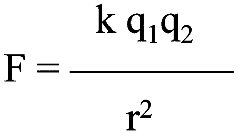
Where k is a constant of proportionality which is analogous to G. It has a value of 9E9N2kg2C-2
It is in fact made up of a combination of further constants making the full formula:
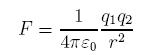
Putting in the relevant signs on the charges gives you a negative number for 2 opposite charges (an attraction) and a positive number for 2 alike charges (repulsion). This differs from gravitation where there is only one type of mass to deal with.
We then looked at the shape of electrostatic field lines.
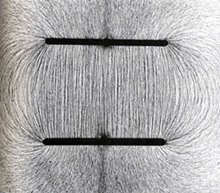
Field lines are parallel here, shown by floating semolina which aligns itself with the field due to an induced dipole being created by the field.
Electric field strength is measured in N/C and is analogous to gravitational field strength. It is not the same as voltage.
Voltage measures the electrical potential energy per Coulomb of charge, not the force. In a uniform field (like between the parallel plates) the field strength is the same at all places, whereas the voltage rises linearly with distance.
So to summarise: electrical force = field strength * charge
electrical potential energy = voltage * charge
Around a point or spherical charge, an oppositely charged particle can perform circular motion, as the electrostatic force can provide the centripetal force required.
No, clearly. Make sure you have shaken off Christmas pie based lethargy and you can define SHM, explain why circular motion exhibits acceleration at constant speed, what resonance is, what angular speed is and give examples of wave-particle duality for light and electrons all in less than 10 seconds.
Revision - Jan '07 mark schemes are on the pupils area.
Good luck all.