| 1987 TII Logic Module Wiring |
| Code BK BR DB DG GY |
| COLOR Black Brown Dark Blue Dark Green Grey |
| Code LB LG OR PK RD |
| COLOR Light Blue Light Green Orange Pink Red |
| Code TN VT WT YL |
| COLOR Tan Violet White Yellow |
| RED CONNECTOR |
| PIN 1 2 3 4 5 6 7 8 9 10 11 12 13 14 15 16 17 18 19 20 21 22 23 24 25 |
| Wire Gauge 20 22 20 22 22 22 18 18 22 18 20 22 20 22 20 18 20 18 20 18 20 18 18 18 18 |
| CIRCUIT K8 K16 Y1 K3 R31 K15 K14 K14 G7 N7 DK21 T21 DK20 Z6 Y4 N4 K19 N1 Y6 N3 C27 N2 N6 K5 N5 |
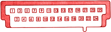 |
| Wire Color VT/WT VT/YL GY/WT BK/PK DG/OR YL DB/WT DB/WT WT/OR GY/BK PK GY/LB LG LB/BK LB BK/YL DB/YL GY/RD LG/BK VT/BK DB/PK BR/WT OR BK/WT BK/LB |
| Wire Color 5.0V Power to MAP Sensor Injector Control Signal Injector On Signal Powr Loss/Check Engine Lamp Signal Voltage Regulation Signal Anti-Dwell Signal Ignition Feed (J2) Ignition Feed (J2) Speed/Distance Sensor Signal Ignition Reference Sensor Serial Communications Interface (TX) Tachometer Gauge Signal Serial Communications Interface (RX) Navigator Fuel Monitor Signal Barometric-Read Solenoid Signal AIS Motor Signal(Winding 2) ASD Relay Signal AIS motor signal (Winding 2) Wastegate Solenoid Signal AIS motor (Signal 1) Radiator Fan Relay AIS Motor Signal (Winding 1) 8V power supply from power module Signal ground at fuel rail bolt Signal ground to sensors |