Trusses:
It can be seen from the stress distribution of a loaded beam that the
greatest stress occurs at the top and bottom extremities of the beam .This led
to the improvement on a rectangular section by introducing the l-section in
which the large flanges were situated at a distance from the neutral axis. In
effect, the flanges carried the bending in the form of tension stress in one
flange and compression stress in the other, while the shear was carried by the
web. For these situations where bending is high but shear is low, for example in
roof design, material can be saved by rising a framework design.
Before discussing more trusses let us know some basic parts and types of
trusses.
considering very simple truss the vertical member is called web and the side
members are called upper cords and horizontal members can be termed as lower
cords for better understanding of the truss components check this figure out.

For enlarges
view click this Fig.
Now as we know the mail components of a truss let us gain some knowledge
about some types of the truss. Flowing Figs can very easily explain some very
basic types of trusses.

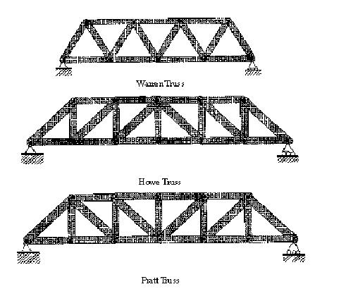
CLICK PAGE 1
CLICK PAGE 2
There are also some specific types of trusses mainly named as
Light Frame Trusses
Light
frame trusses are made from dimension lumber of various sizes. The chords and
webs are connected together by the use of toothed connector plates which
transfer the tensile and shear forces. The connector plates are stamped from
galvanized steel sheet metal of different grades and gauge thicknesses to
provide different grip values. Design of these trusses is usually done by the
truss manufacturers using computer software developed by the truss plate
manufacturers. Other custom developed structural analysis software is also used.
Heavy Timber Trusses
Heavy timber
trusses are made from timbers, or from manufactured wood products, such as
glulam or parallel strand Iumber (PSL), havlng the dimensions of timbers.
Connections for members are made by using bolts and plates, split rings and
special brackets and hangers. Heavy timber trusses provide long spans for
applications where the space required for the depth of the trusses can be
accommodated into a building plan.
For their
more details

Now as we know all basic components about truss let us discuss how load is
supported by the truss.
A truss concentrates the maximum amount of materials as far away as possible
from the neutral axis. With the resulting greater moment arm (h), much larger
moments can be resisted.
Resistance of a truss at a section is provided by:
M = C x h = T x h, where C = T in parallel cords and:
C = compression in the top chord of the truss.
T = tension in bottom chord of a simply supported truss.
h = vertical height of truss section.
If either C, T or h can be increased, then the truss will be capable of
resisting heavier loads. The value of h can be increased by making a deeper
truss.
Allowable C or T stresses can be increased by choosing a larger cross
section for the chords of the truss, or by changing to a stronger material.
A framework or truss can be considered as a beam with the major part of the
web removed. This is possible where bending stresses are more significant than
shear stresses. The simple beam has a constant section along its length, yet the
bending and shear stresses vary. The truss, made up of a number of simple
members, can be fabricated to take into account this change in stress along its
length.
The pitched-roof truss is the best example of this, although the original
shape was probably designed to shed rain water. Roof trusses consist of sloping
rafters which meet at the ridge, a main tie connecting the feet of the rafters,
and internal bracing members. They are used to support a roof covering in
conjunction with purling, which are members laid longitudinally across the
rafters, the roof covering being attached to the purling. The arrangement of
internal bracing depends on the span. Rafters are normally divided into equal
lengths, and ideally, the purlins are supported at the joints, so that the
rafters are only subjected to axial forces. This is not always practicable,
since purlin spacing is dependent on the type of roof covering. When the purlins
are not supported at the panel joints, the rafter members must be designed for
bending as well as axial force. The internal bracing members of a truss should
be triangulated and, as far as possible, be arranged so that long members are in
tension and compression members are short to avoid buckling problems.