Pictures of Gasket for 7JP4 CRT
Well here are the pictures as promised. I didn’t get my digital camera back so I shot These with my 35mm and scanned them. They came out a little dark so I touched them up in Photoshop. You can get a better idea what this gasket looks like. I am looking into Re-making these Gaskets. I have a friend that works for the studios here in Southern California in the make-up and props department and can most likely (if he can get the time) help me created a mold and also offer me advice on what material would hold up better than the original. If or when it happens I'll post to the news group, as I know there are a lot of bad gaskets in these Televisions. Enough of the yakking...on to the pictures !!
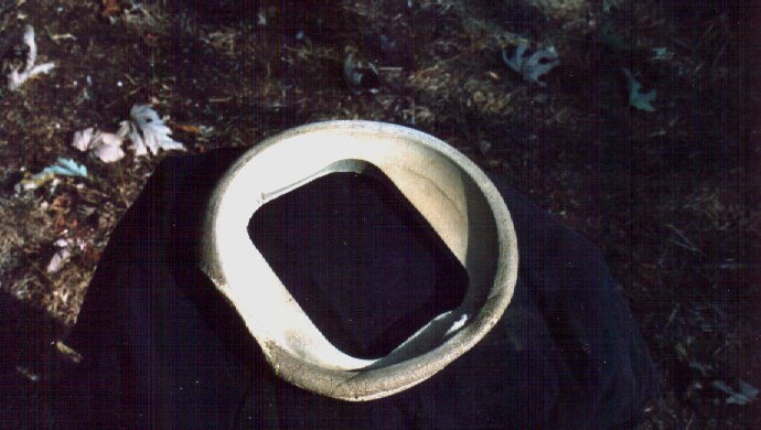
This is a shot of the gasket side that faces the CRT. The Flat area goes to the top of the Cabinet. Notice that it is cupped to hold the CRT in place .
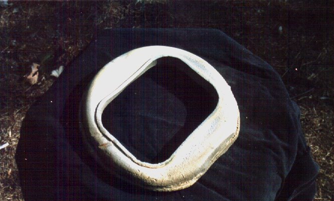
This side faces the outside of the Cabinet.
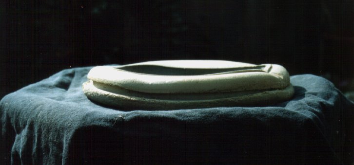
Here is a side view of the gasket. Note the grove in the middle; this is how it inserts into the cabinet. Similar to how windshield molding holds auto glass.
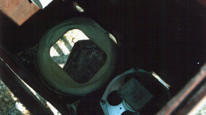
Here is an inside view of it installed in the cabinet.
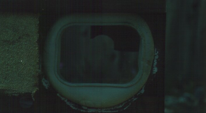
Here is an installed outside view of the CRT gasket. You can see where some of the original gasket deteriorated and is still fused to the wood around the gasket currently installed.
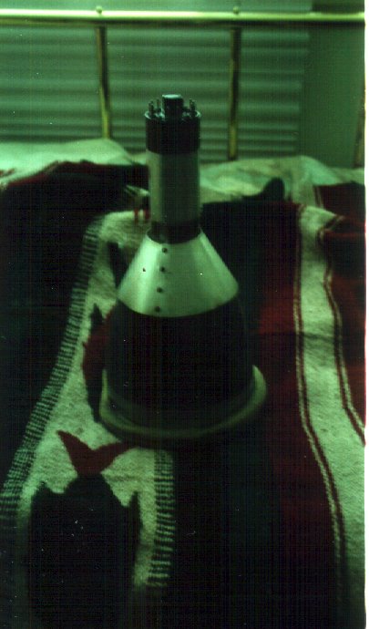
Here is a view of the gasket with the CRT standing face down in it. Note the shields on the 7JP4 CRT. There was also cardboard between the rear mount and the neck of the CRT with the shield installed of course. I don't know if Motorola ever made the CRT's for this television I have 4 of these sets and the count so far is 2 RCA's 1 Sylvania and a Philco from my records of CRT's installed in them when purchased.
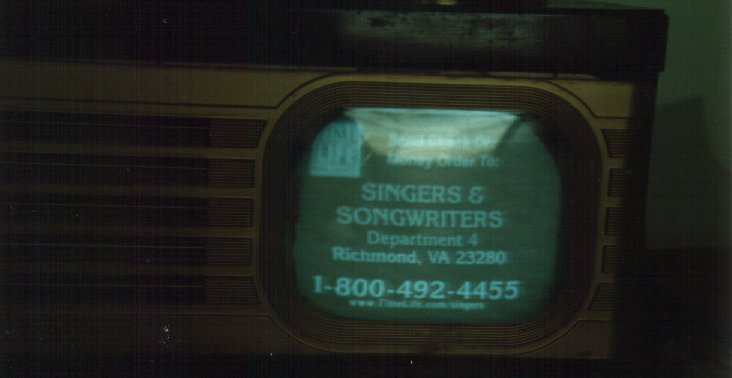
And last but not least here is the VT-71 that I use a few hours every week (again sorry about the poor quality of the picture). It has the TS-4J Chassis. I electrically restored it by first cleaning the Pots and switches with De-Oxit. Then I installed all new Capacitors with many thanks to the kind people on the news group who pointed me to the correct place Allied Electronics to purchase the many 6000volt capacitor I needed to rebuild four of these sets. I also changed out any out of spec. Resistors, replaced the Selenium Rectifiers with Silicone Diodes and finally replaced any weak tubes. I usually start with repairing the power supply and any obvious defect and firing up the set using a variac along the way to see my progress. This time I waited till I had replaced and repaired everything. When I fired up the set (using an Isolation Transformer and Variac of course) I was please to see it come right to life. It didn't take more than 30 seconds after it warmed up to have all of the controls adjusted for what is a surprisingly decent and stable picture for a 53-year-old television (This picture does not do it justice as all four sides of the picture are very straight and not jagged on the left as in this picture). I really enjoyed working on this set and if I can ever get my Digital Camera back from my Father I’ll take pictures of the next one while restoration is in progress.
Happy Collecting Everybody!!
Regards, Steve.
Contact Information
©2002 Steven W. Reeves