G. E. M. (Generadores eléctricos por fuerza mareomotriz)
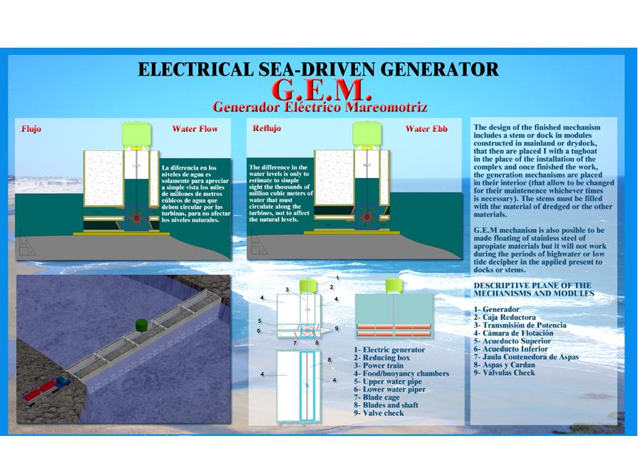 G. E. M. Generator ELT by Sea power This mechanism allows to take advantage of the submarine currents to make work turbines that produce electrical energy. It works in any place where the topography of the place allows it, channels, rivers, coves, gulfs, etc. and smaller topographic accidents. Another G.E.M modality (floating of stainless steel) can be applied to coasts of moderate slope and rivers of slow current. Trigger of the project: this simple mechanism was imagined, when I observed that the currents of the tides did not allow my plummet to anchore in the floor of the small rivers in Bahia Blanca without being dragged before by the current. While in the surface ,our small boat practically did not move, according to the table of the seas i realized that in approximately five hours the water moved with this current filling hundreds of hectares in each high water. With these elements, plus my previous experience of several years tying to develop my other inventions to take advantage of the force of the sea, the Marine Siphon and the Marine Lung (to see Web site: www.rebich- and the Marine Lung (to see Web site: www.rebich-inventos.8k.com) I worked to develop the G. E. M. convinced that this incalculable force that drags a plummet, could rotate great vanes of several hundreds of meters or kilometers, whose power must be evaluated by specialized scientists and equipment. The design of the finished mechanism includes a stem or dock in modules constructed in mainland or drydock, that then are placed l with a tugboat in the place of the installation of the complex and once finished the work, the generation mechanisms are placed in their interior (that allow to be changed for their maintenance whichever times is necessary). The stems must be filled with the material of dredged or the other materials. A G.E.M mechanism is also posible to be made floating of stainless steel of apropiate materials but it will not work during the periods of highwater or low tide because it does not counts with an unevennesses reserve like the G. E. M I decipher in the applied present to docks or stems. Descriptive plane of the mechanisms and modules Suggestions for its construction: A Stem or a dock should be made in the place that technically is more advisable according to the specialists in ports and technicians. A- If it is necessary, the floor with reinforced concrete in a place is due to prepare where the low tide surpasses the 2 mts on the level of the floor. B- To place the modules that are necessary to form the aqueducts, one inferior (6) and another superior one (5), with a conduct of a meter high each one, and 10 mts length by 12 mts. of wide (estimative meassures acording to the place). Between the central ends of the conducts to leave a separation of 2.20 mts (the turbine will be placed there). Next to place the conducts with a 1.50 length mts, conserving the level and the line among them. C- In the inferior conducts (6) to place valves of exit to the submarine current. In the superior conducts (5), to place entrance valves (these will always have to respect the circulation of the turbines). D- The amount of conducts and size of their aqueducts must be considered so that they allow to pass the great volume of water that will circulate around the inferior conducts (6), to fill the rivers.The same effect will take place with the superior conducts (5) when the tide is low , If it is not possible to be calculated the cubic meters of water that travel through the conducts of the culverts it is necessary to place automatic floodgates so that they regulate the passage of the sea. This way both sides of the stem will maintain their natural. Structure of the turbines: simple positioning or extraction for maintenance. Once supported on the concrete floor of the modules they are ready for their operation. The hollow Module (pontoon) of reinforced concrete of high quality, fills with rocks, stone, etc. When they are united forming a stem or peak they form a way/rails to cross the river or a part of it to make the installation and maintenance. If its settled in opened places, for example in great coves one of its ends must finish with an Y shape with arms of several meters. The Hole of precision in its interior allows to place or to remove the turbines for the maintenance. How to build the G.E.M To choose the place that technically is more advisable to install the G. E.M., and to determine the measurement of open sea and water volume that is needed to fill the cove, channels, etc. With these measures, determine the amount of aqueducts and size of the generating conducts of electricity, so its possible to add great conducts with automatic doors to control the natural level of the water to both sides of the stem. G. E. M Finished on a river I) The planes are detailed in this file. II) Prepare a place in mainland or the drydock next to the sea with a slope that allows to hurl to the water the floating modules to be constructed in that place. III) Make the base (according to the plane) of reinforced concrete special. Place on this base the aqueducts constructed with special molds (of 6 mts more 1.50 mts). On this base to construct the structure of the plane (wide considered: 13 mts, length: 15 mts with hollow -4-, height according to tide), and one opening of precision: 2,20 by 6.40 mts (cage 7), to fix the turbines. IV) When all the necessary modules are ready, hurl them to the water and tow them to the correct place, fill them with water so that they get attached to the floor two meters or more of the level of low tide. V) Finish placing all the modules correctly until the stem is completed. Introduce reinforced plastic bags (closed tubes) in the three holes that the union of the modules. Fill these bags with quality concrete. This material should mold to the surface of the floor, without breaking the plastic, forming a leg or pilots to anchor and to support the weight of the stem. Immediately fill with rocks, stone, etc. the floating holes or cameras. It is possible to decide the length that is necessary, without closing all the cove. In this case the stem with must be finished with an Y shape as it has been already mentioned. With this alternative the turbines will only work when the tides are changing, without being able to regulate the time of open sea or low tide, that is obtained with the complete closing of rivers, channels, etc. All the industrial systems that generate electrical energy based on nonrenewable fuels with great dimentions as dams or nuclear plants. etc. represent extraordinary investments. I consider that the mechanisms referred here must be considered and evaluated, to take advantage of the incalculable force of the sea and wind,that nature gives to humanity to generate clean energy without contaminating our punished planet. Mecanismo que permite aprovechar las corrientes submarinas para hacer funcionar turbinas que producen energía eléctrica. Funciona en cualquier lugar donde la topografía del lugar lo permita (canales, rías, ensenadas, golfos y accidentes más pequeños). FUNCIONAMIENTO: Se debe hacer espigones, tajamares o un dique que permita trabajar simultáneamente los dos mecanismos (el G.E.M. y el Sifón Marino) el el lugar que técnicamente sea más conveniente según los especialistas en puertos y técnicos. A- Se debe preparar el piso con hormigón armado en un lugar donde la bajamar supere los 2 mts sobre el nivel del mismo piso. B- Colocar los acueductos que sean necesarias, una inferior (6) y otra superior (5), con un ducto de 1 metro de alto cada una, y 10 mts de largo por 12 de ancho (ver plano). En los extremos de las alcantarillas dejar una separación de 2,20 mts (allí se colocará la turbina). A continuación colocar las mismas alcantarillas con un largo de 1,50 mts, conservando el nivel y la línea de los ductos. C- En los ductos inferiores (6) colocar válvulas de salida de la corriente submarina. En los ductos superiores (5), colocar válvulas de entrada (estas siempre deberán respetar la circulación de las turbinas). C- La cantidad de ductos y tamaño de sus acueductos deben estimarse de manera que permitan pasar el gran volumen de agua que circulará por los ductos inferiors (6), para llenar las rías o ensenadas. El mismo efecto se producirá con las ductos superiores (5) cuando baja la marea. Si no se puede calcular los metros cúbicos de agua que transitan los ductos de las alcantarillas hay que colocar compuertas automáticas para que regulen el paso del mar. De esta manera ambos lados del tajamar mantendrán su nivel natural. (FOTOS) Estructura de las turbinas, de sencilla colocación o extracción para mantenimiento. Una vez apoyadas sobre el piso de hormigón quedan listas para su funcionamiento: 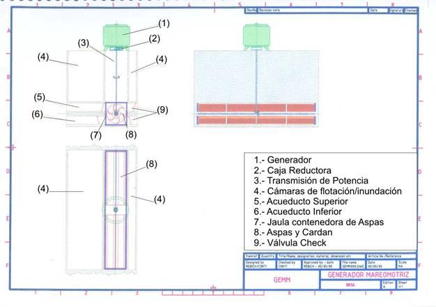 Detalle y referencias 1- Alcantarillas de ingreso del mar a la ría o ensenada. 2- Alcantarillas de salida. 3 y 4- Salientes para válvulas y orientación de la corriente. 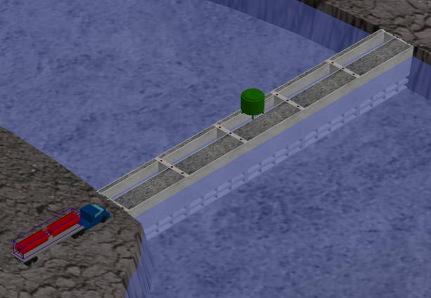 5- Válvulas que funcionan por efecto de las corrientes submarinas. 6- Sistema de transmisión. 7- Paletas que funcionan por la corriente marina. 8- Cardan y caño cubre-cardan. 9- Mecanismo que da velocidad a los generadores de electricidad. 10- Generador de electricidad. 11- Rieles para grúas. A- Módulo hueco (prontón) de hormigón armado de alta calidad, que se llena con tosca, piedra, etc. cuando se encuentran unidos formando un tajamar o espigón (camino o rieles para crzar la ría o ensenada) o parte de la misma que debe terminar en una "Y", con brazos de varios metros. B- Hueco de precisión, que permite colocar o sacar las turbinas para el mantenimiento. . 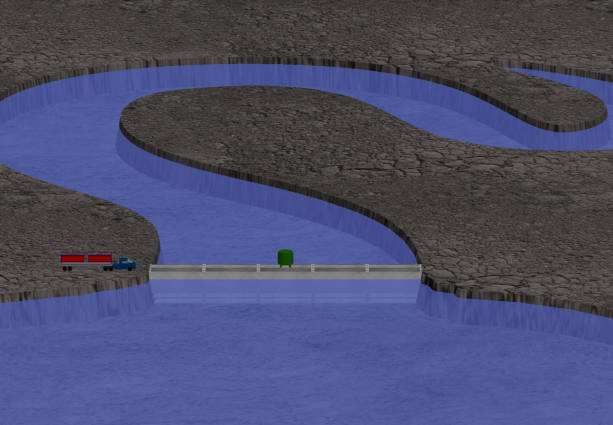 . CÓMO SE CONSTRUYEN LOS G.E.M. Sugerencia para construír un tajamar y los mecanismos que permitan hacer funcionar los G.E.M. (n° 1), que deben ser evaluados por científicos y expertos en puertos. 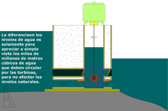 . 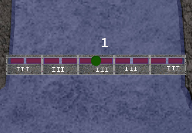 Elegir el lugar que técnicamente sea más conveniente para instalar los G.E.M., y determinar la medida de altamar y caudal de agua que tiene que circular para llenar la ensenada, canales, etc. Con estas medidas determinar la cantidad de acueductos y tamaño de los ductos generadores de electricidad, y agregar grandes ductos con puertas automáticas para controlar el nivel natural del agua a ambos lados del tajamar. Cómo hacer un tajamar con todos los mecanismos del G.E.M. N° 1 A) Ver planos. B) Preparar un lugar en tierra firme lo más próximo al mar y con una bajada que permita botar al agua los módulos flotantes a construírse en ese lugar. C) Hacer la base (según plano) de hormigón armado especial. Colocar sobre esta base los acueductos construídos con moldes especiales (de 6 mts más 1,50 mts). Sobre esta base construír la estructura del plano (ancho estimado: 13 mts, largo: 15 mts con hueco -4-, altura según marea), y una abertura de precisión: 2,20 por 6,40 mts (jaula 7), para fijar las turbinas. D) Cuando todos los módulos necesarios estén listos, botarlos al agua y remolcarlos hasta el lugar correcto, llenarlos con agua para que se fijen en el piso a dos metros o más del nivel de bajamar. E) Terminar de colocar (F) todos los módulos correctamente hasta que quede el tjamar completo. Introducir bolsas de plástico reforzado (tubos cerrados) en los tres huecos que tiene la unión de los módulos. Llenar estas bolsas con hormigón de calidad. Este material se debe amoldar a la superficie del piso, sin romper el plástico, formando una pata o pilote para anclar y soportar el peso del tajamar. Inmediatamente llenar con tosca, piedra, etc. los huecos o cámaras flotantes (4). Se puede optar por el largo que sea necesasrio, sin cerrar toda la ensenada (en este caso debe terminarse el tajamar con una "Y", con cada brazo de varios metros. Con esta alternativa las turbinas sólo funcionarán cuando las mareas suban o bajen, sin poder regular el tiempo de altamar o bajamar, que sí se logra con el cierre completo de rías, canales, etc. Próximamente estará en esta página el GEM 2, transportable, para usar por particulares o pequeños grupos de viviendas en playas y otros lugares de poca profundidad del mar; y también un mecanismo para ríos de llanuras. G.E.M FLOTANTE PERMITE SER ANCLADO EN CUALQUIER LUGAR MAR Y APROVECHAR LAS CORRIENTES DE LAS MAREAS Y OTRAS PAR GENERAR ENERGIA ELECTRICA. Este mecanismo G.E.M. esta constrido de acero inoxidable, o el material que técnicamente sea más conveniente, cuyos laterales de cada modulo son flotadores huecos de aproximadamente 12 mts de largo por una altura(profundidad) de aproximadamente 6 mts. con hueco de 0,30/40 mtas.que permite agregar agua, cuyo peso determina la altura y la estabilidad necesaria. ( ver planos del G.E.M.) Este modelo de G.E.M. funciona únicamente 16/18 hs, y su tamaño es de uno ó dos módulos construidos con material de calidad, y pueden trabajar infinita cantidad de de estos G.E.M en un sector determinado. El traslado para ubicación ó mantenimiento lo pueda hacer cualquier embarcación mediana. El mecanismo G. E. M. FLOTANTE, sin los ductos funciona correctamente las 24 hs. en ríos navegables, o ríos pequeños de agua lentas. . . |