If you watched the video above you have an idea of how hard it came
down.
I knew the R7C chute was pushing it but I didn't know how much.
I
have since replaced it with an R9C to give it a softer landing.
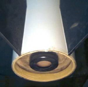
The tail end
was a bit smashed but since I glassed the BT it was minimal.
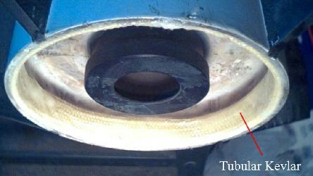
Beefing up the tail
I decided to beef up the end so it could take the occasional
hard landing better.
I had some 5/8 tubular
Kevlar so I used that to strengthen the BT end.
I used West system epoxy to
epoxy it in place.
|
|
Positive NC attachment
I also decided to add a nylon bolt to hold the NC on.
To accomplish this I
got some 2-56 nylon screws and a tap.
Using plastic welder(epoxy) I glued a
piece of brass plate to the NC shoulder.
I drilled through the BT into this
brass using a 1/16in drill bit.
I then tapped the NC side and made the BT
side a little bigger.
Now I can hold the NC on by threading a Nylon bolt in
that will break at motor ejection.
Altimeter bay
When I built the Terrier I kept in mind that I might want to add an altimeter
bay to it.
Well I was reading a rocket magazine and there was an article that
stated Hypertek was giving away reloads for certification flights.
This made
me decide to add the altimeter bay just so it was available if I needed to use
electronic ejection. Also I might want to use electronic ejection because its
hard to simulate how long a delay to use for the motor. With electronic ejection
it would pop the chute at apogee.
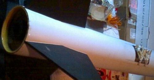
I cut a hole in the BT just below the upper
centering ring. I figured I would mount a plywood plate to the MMT
there.
Using my dremel with a cutoff wheel I carefully cut a hole in the
airframe.
I removed this section and cut a piece of 5in coupler so that there
was 1/2in overlap at the top & bottom and 1in at the sides. I also cut the
center section of this coupler piece so it would overlap the hatch by 1/4in
I
then took a 1in thick pine board and cut triangles out so the hypotenuse
was curved like the motor tube. These four pieces were white glued to a piece of
plywood that would act as the mount point for the altimeter. I put epoxy on the
pine wedges and mounted the assembly into the altimeter bay. Once dry I pried
the plywood off. That white glue was stronger than I thought it would be, note
to self ,"Use hot melt glue next time".
Placing the plywood back in place I
drilled 4 holes for wood screws to mount it with.
I took the piece of BT that
was cut off(the hatch) and marked locations for holes and drilled through it
into the coupler piece.
I then took the couple piece and epoxied on 4 tee
nuts to the back side of it. I mounted these backward because the material
wasn't thick enough and the end of the tee nut would have stuck out so I mounted
it so the spikes were pointed away from the coupler. This gives something for
the epoxy to bite into.
I then bolted the hatch to this piece of coupler,
added some epoxy to the lips sticking off and finagled it into the BT.
Before
the epoxy hardened I removed the bolts one at a time and added a fender washer
to it and reinserted it. This kept the hatch level with the surface of the BT
while the epoxy dried.
Once
dry I removed the hatch and added more epoxy and clamped it down.
 |
 |
I used West systems epoxy, because its very
thin, so it could work its way inside. I also brushed it on the inside of the
hatch to harden it.
I was concerned about the integrity of the body tube since I
just cut a big hole in it. I was concerned that a less than stellar landing
might crimp the tube opposite where the hatch is.
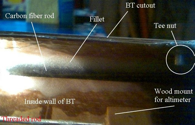
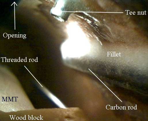
Beefing up the BT
I thought about adding a strip of carbon fiber inside the airframe neer the
hatch. This seemed impossible to do through the opening.
I then recalled that
I had some carbon fiber rod. This was 1/4in in diameter and not coated. It was
not an arrow shaft but a hollow rod used in R/C aircraft.
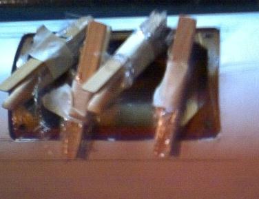
I cut two lengths
10" long and tacked them into the airframe on either side of the opening using
5min gel epoxy. I put a dollop of epoxy on each end of the rod. Then carfully
positioning the rod in the airframe where I wanted it I rolled it so the epoxy
would make a dam at the ends. This dam was to keep the West systems epoxy from
running off the end.
After the 5min set up I mixed up some West
systems and mixed in some filler. I applied this to the rod so that it would
make a fillet and I then applied some to the other side of the rod using my
gloved hand. This will be very strong and still didn't add too much weight.
 |
 |