Fincan Painted
Components
Basic design(PDF file)
Construction Details
Items with links are done.
1) Makeing fins
2) Apply CF to BT's
3) Assemble fincan
4) Electronics
5) Other
Additional mods...
Statistics:
Weights:
| Part | Weight | Total |
| Fincan | 9lb 4oz | 9lb 4oz |
| Upper half | 6lb 13oz | 16lb 1oz |
| Electronics bay | 3lb 14oz | 19lb 15oz |
| Motor case | 11lb 6oz | 31lb 5oz |
| Propellant | 39lb |
These fins were scaled up from the sustainer fins.
I used 1/16in thick G10 and 1/8in thick nomex honeycomb.
There
are two pieces of the honeycomb one on either side of the G10.
The honeycomb is cut smaller than the
G10 so I can make a taper with expanding foam.
I layed up the fins with two layers of 8oz CF on each side
with the weive of the inner layer at 45deg to the outer layer.
I used a 500deg stable epoxy to layup the fins.
I wanted to use phenolic tubes covered with layers of carbon.
But because
the OD of the case was exactly the same as the ID of the 6in tubes I got I could
not use these tubes.
I decided to use the motor case as a mandrel and rolled
my own tubes.
I wrapped the motor case with Polyethylene film to prevent the layup from sticking and also to build a known thickness up so the case could slide into the tube when its all done.
Over this I put two layers of 20oz fiberglass, two layers
of 8oz CF and two layers of 5.7oz CF.
This gave me a final tube wall
thickness of just over 0.1in.
Because the fins were going to be attached to the outside of the lower BT and the fins used 500deg stable epoxy I decided I had to use the same epoxy for at least the lower BT. The upper tube was done with West Systems epoxy.
The first step in assembling the fincan was to surface
glue the fins to the body tube.
I created a paper wrap to go around the body
tube so I could align the fins.
Each fin was tacked in
place with CA glue.
Once they were all attached I put a generous fillet.
This was again the
500deg stable epoxy with Kevlar pulp added.
Next I applied two layers of 6oz s-glass from fin tip to fin tip across the BT.
I drilled and tapped two 1/4in holes in the airframe for rail
buttons.
I bolted them on, then ground down the excess from the inside with
my dremel.
After paint I will epoxy them in
place when threaded through the airframe.
I then proceeded to sand , fill and prime it.
The sustainer was flourescent
red/orange so I painted the booster flourescent yellow.
Fincan Painted
I made an electronics bay that slips in above the recovery bay and bolts
below the transition where the sustainer sits.
I used a 4in piece of phenolic
coupler tube that I glassed on the OD.
I attached 3 steel supports to the
inside of this tube to transfer the thrust from the motor to the sustainer.
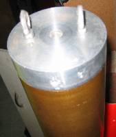
I
used two 1/2in aluminimum bulkplates for this bay.


Booster ebay
Recovery:
For primary
dual deployment I used the acceleration based PICO-AA2.
I also used an
PICO-AA1 as a backup timer for apogee.
Recovery electronics
Location:
I installed an
APRS setup to aid in recovery.
This used an OEM board GPS with a geohelix
antenna, a TT3 and a Alinco transmitter.
This was setup to transmit position
reports every 2seconds.
It also transmitted on the same channel as the
sustainer so it could use common ground stations.
The sustainer system was setup to monitor the radio and if
the channel was in use due to the booster transmitting it would wait till the
channel was free.
I needed to be able to screw the GPS and TX antenna on
after the electronics bay was installed so they would stick out of the CF
airframe.
In the
photo you can see the Tx w/o an antenna.
GPS telemetry setup
I needed to build a crate to ship the booster fincan to CA.

Booster crated
Since I was using headend ignition I had to rig up a new
way for the harness to attach to the top of the motor in the sustainer.
I
made an aluminum ring that was the same OD as the bulkhead so it could sit below
the snapring in the case.
This ring had a hole in the middle big enough for the
ignitor wires to feed through.
The shearpin block was attached to this
new ring with two forged eyebolts.
New attachment point
I also rearranged the electronics in the sustainer
nosecone.
In the photo you can hardly tell there are two PICO-AA1's
stacked.
One is the backup deployment timer and the other is for sustainer
ignition.
I used a CO2 deployment for apogee backed up with a BP charge.(not
shown)
I swapped out the Alinco DJ-4C for the DJ-S40.
I also replaced the Deluo GPS with a better Sony model
using a Geohelix antenna.
The Sony has a backup battery so it gets lock much faster.
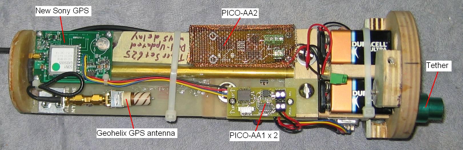
Sled front
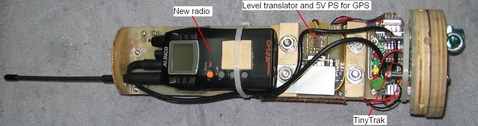
Sled back
I had to sand down the OD of the base of the sustainer
so it would fit in the booster.
The transition was designed so the base of
the sustainer fits inside the booster.
The base of the sustainer is wrapped
with a piece of teflon sheet to allow it to slip out easily.
For a perfect
fit I had to sand down my freshly painted sustainer.
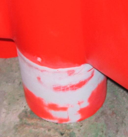
Sanded