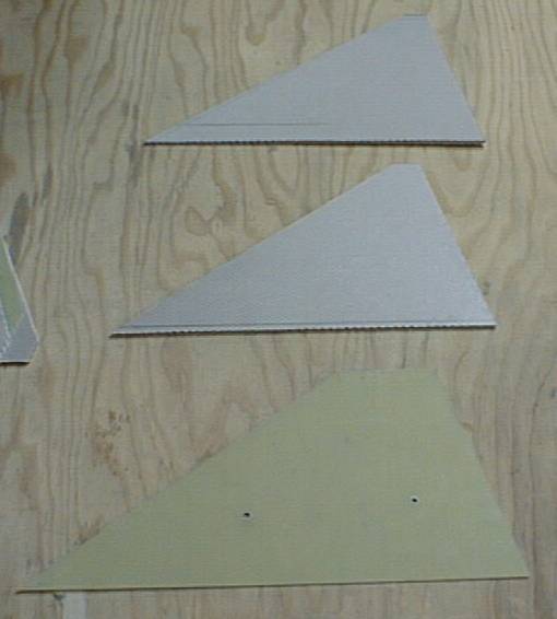
Fin pieces
Components
Basic design(PDF file)
Construction Details
Items with links are done.
1) Makeing fins
2) Apply CF to BT's
3) Assemble fincan
4) Electronics
5) Nosecone
Additional mods...
Statistics:
Weights:
| Part | Bare | With Glass/CF | Total |
| NC | - | 1lb 5oz | - |
| Assembled nosecone E-bay | - | 2lb 10oz | 2lb 10oz |
| Upper tube | - | 2lb 3oz | 4lb 13oz |
| Fins(3) | 1lb | 1lb 7oz | - |
| Assembled fincan | - | 4lb 4oz | 9lb 1oz |
| Main parachute/harness | 2lb 7oz | 11lb 8oz | |
| Shear pin block | 1lb 6oz | 12lb 14oz | |
| GPS telemetry | 6.5oz | - | |
| Motor hardware | 12lb 6oz | - | |
| Propellant | 15lb | - |
As with many of my projects I decided to try something new with this one.
I wanted to try nomex honeycomb for fins.
I came up with the idea to use
thin honeycomb and thin G10 in a sandwich.
The G10 would create a strong edge
and the honey comb would strengthen the thin G10.
I selected 1/16in thick G10 and 1/8in thick nomex honeycomb.
There would
be two pieces of the honeycomb on either side of the G10.
The honeycomb would
be cut smaller than the G10 so I can make a taper with expanding foam.
Fin pieces
Fin test fit
I glued the pieces of the fin together with normal west systems epoxy.

Fin pieces glued
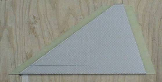
I poured two part expanding foam onto the G10 so it would expand to fill the gap between the G10 edge and honeycomb edge.

Fin foamed
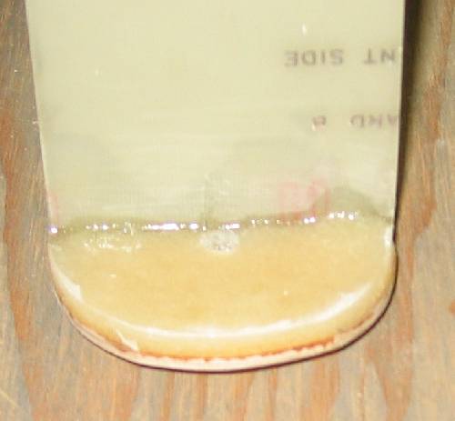
I trimmed the foam with a hotwire and finish sanded it with 60grit paper.

Fin carved
There were some larger voids in the foam.
I masked off the fin with tape
then I mixed up some epoxy and added microballoons to make it easy to sand.
I
squeegied this onto the edge and let dry.
Once dry it was easy to sand to
shape.
This is the only application for microballoons in rocketry.
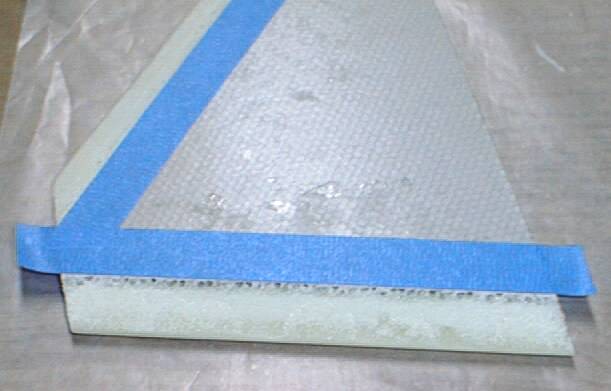
Fin showing holes
I layed up the fins with two layers of CF on each side
with the weive of the inner layer at 45deg to the outer layer.
I used a
500deg stable epoxy to layup the fins. My concern was because the fins were
going to be attached so close to the nozzle in the 4in motor.
500deg stable
is way more than needed but is much better than the 120deg value of the west
systems epoxy I normally use.
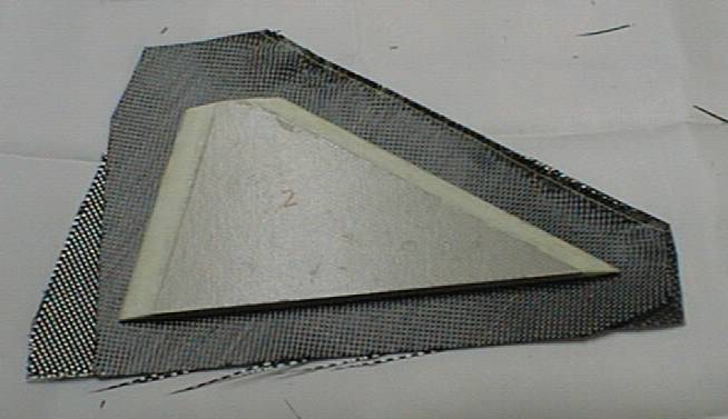
Laying up CF
Once the layup was complete I vacuum bagged the fins.
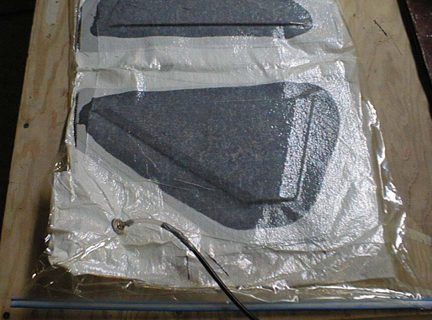
Fin bagged
Here is a complete fin after removal from the vacuum
bag.
Looks great!
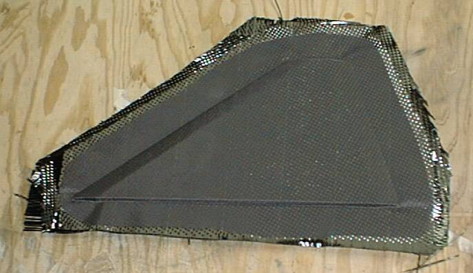
Fin removed from bag
I trimmed the excess with my dremel. Very nice.

Fin trimmed
Because the fins were going to be attached to the outside of the lower BT and the fins used 500deg stable epoxy I decided I had to use the same epoxy for at least the lower BT.
Here is a photo of the lower BT with two layers of CF applied.
I used
heatshrink tape and my curring oven to process this tube.

BT with CF applied
The first step in assembling the fincan was to surface
glue the fins to the body tube.
I created a paper wrap to go around the body
tube so I could align the fins.
Each fin was tacked in
place with CA glue.
Once they were all attached I put a generous fillet.
This was again the
500deg stable epoxy with Kevlar pulp added.
If you have ever worked with Kevlar pulp you know it generally does not make
a nice smooth fillet as other fillers do.
I came up with the idea of cutting
strips of release cloth and laying them over the fillet so I could smooth it
with my gloved hand. Then once cured I peeled back the cloth to expose a
prefectly shaped fillet.
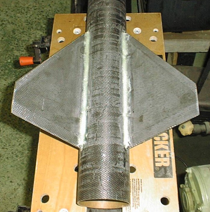
Kevlar fillets
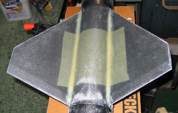
Fins glassed
I drilled and tapped two 1/4in holes in the airframe for rail
buttons.
I bolted them on, then ground down the excess from the inside with
my dremel.
After paint I will epoxy them in place when threaded through the
airframe.
I then proceeded to sand , fill and prime it.
My wife picked
out a nice Flourescent Red/Orange paint for it.
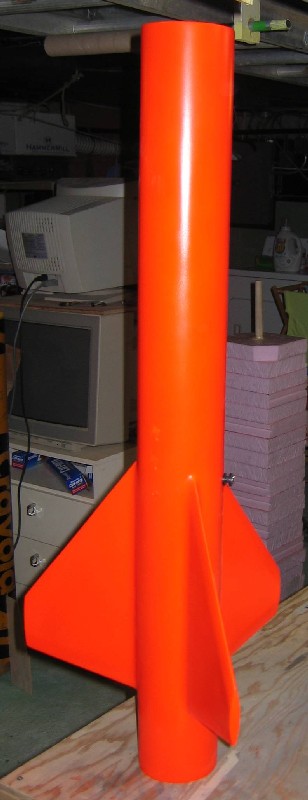
Fincan Painted
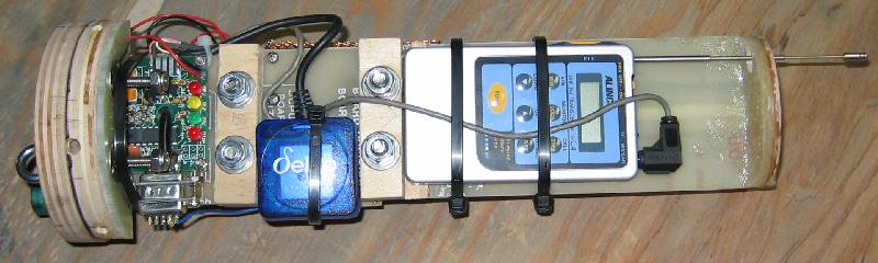
Recovery:
I built a special acceleration based
altimeter for this rocket because of the speeds it will go.
I just didn't feel comfortable using a pressure only based altimeter.
To make programming easier I simply used a 16bit value for the velocity calculation.
This does limit the max velocity the altimeter can experience to 50G for 12sec.
I don't see this as much of an issue.
It records at 200Hz.
There is a built in delay of 15sec after apogee is detected.
This delay prevents the Main altitude from being detected during the apogee seperation event due to the altimeter bay
venting throught he bulkhead into the parachute compartment.
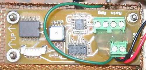
Recovery Accelerometer
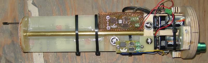
Location:
I was going to use a tracking transmitter in the rocket to help in location.
I decided instead to use GPS telemetry to simply tell me where the rocket is.
This was made easy by using a Tiny Trak 3 from http://www.byonics.com.
The TT3 connects between your GPS receiver and transmitter.
It decodes the GPS data and encodes it as tones that can be sent over a normal radio.
This does require a HAM license to operate but as luck would have it, I have one.
The complete setup with 9V battery is 6.5oz and quite small. The 9V runs the TT3 and GPS.
Since the GPS is a battery hog I might switch to a larger battery pack.
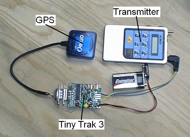
GPS telemetry setup
Inside NC
I built a sled to hold the electronics.
I started by cutting a bulkhead out of 1/2in ply that would just fit inside the sholder of the NC.
I then cut a piece of G10 and glued it to this plate so the threaded rod could pass through.
I also wanted some support at the top of the G10 so it wouldn't rattle around inside so I cut a circle out of 1/8in plywood.
I cut this circle in half and glued half to each side of the G10.
I then slid this into the NC and sanded on the 1/8in ply till it just fit nicely.
This photo shows the sled, with recovery electronics installed and batteries in position.
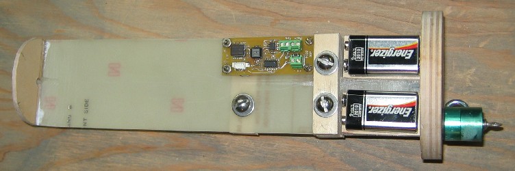
Electronics sled

Reinforcing plate
Forward plate
I mounted the GPS equipment to one side of the sled.
GPS telemetry
Recovery Electronics
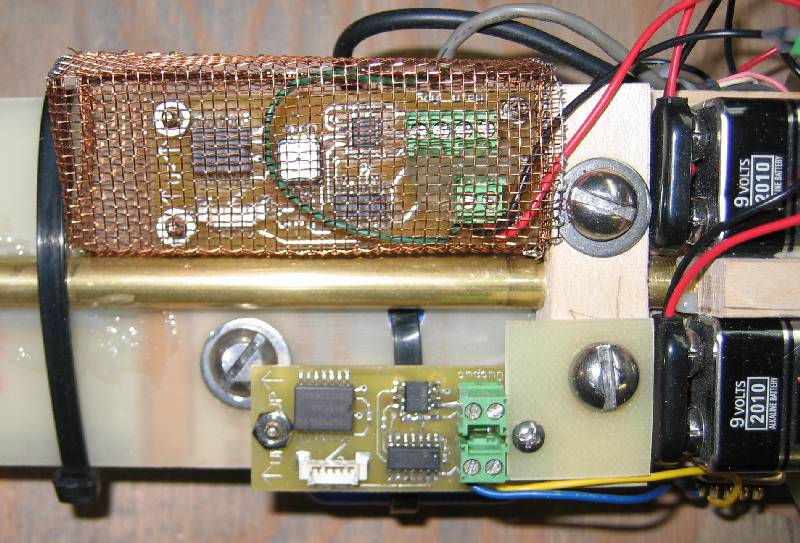
Recovery Electronics

NC
NC bulkplate
I did not take a photo of the other end.
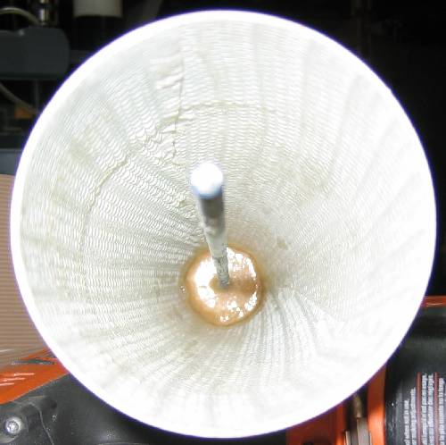
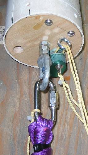
I put a 1/2in forged eyebolt into the front of the motor bulkhead.
This went through an Al block securing the block to the front of the motor.
This block has 3 tapped #4 holes in it for shearpins.
Once the airframe is in place the shearpins hold it on till apogee.
Thanks to Tracy
'Woody' Wood for making the block.