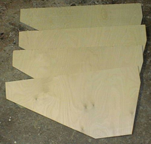
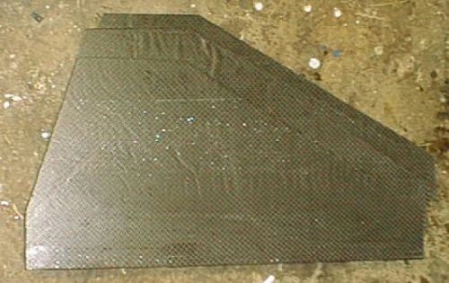
Fins cut out
Components
Basic design(PDF file)
Construction Details
Items with links are done.
1) Cutout fins
2) Cut out CR's
3) Make NC
4) Fiberglass NC
5) Apply CF to fins
6) Put Kevlar wrap on end of tube
7) Fiberglass 3 x 48in BT sections
8) Make Thrust Plate
9) Assemble fincan
10) Cut fin slots in BT
Additional mods...
Flight prep
Flights:
| Location | Motor | Notes |
| LDRS 23 Geneseo,NY 7/3/2004 | AMW N3400RR | Peak altitude 4800' |
Statistics:
I decided to add some statistics of the build.
I used 20yards of 6oz glass and over a gallon of West Systems
epoxy to fiberglass the 3 BT sections and the NC.
I used a whole gallon
of epoxy on just the two BT sections and the NC.
The fincan has 4fins and 4 extension pieces. Each of these have 4 Al brackets. Each bracket has 4 holes. That's a total of 128 1/4in holes I had to drill in the aluminum alone! Not to mention the matching holes I had to drill in the CR's and fins. And they all had to be aligned.
Weights:
| Part | Bare | With Glass | Total |
| NC | - | 10lb | 10lb |
| Tubes(2) | 3lb each | 7lb each | 24lb |
| CR 1&2 | 14oz each | - | - |
| BP's(5-2 for TP) | 1lb 3oz each | - | - |
| TP | - | 2lb 10oz | - |
| Fins(4) | 2lb 5oz each | 2lb 12oz each | - |
| AL brackets(32) | 1oz each | - | - |
| Assembled fincan | 50lb | 74lb | |
| Assembled E-bay | 8lb | 60lb | |
| Drogue section insert | 4lb | - | 64lb |
| Main parachute | 10lb | - | 75lb |
| Nose Weight | 10lb | - | 85lb |
The fins were cut from 1/2in Birch plywood.
I cut the outline of the fins with the jig saw by drawing the pattern on the wood and
cutting on the line.
Fins cut out
I cut the CR's from 1/2in plywood. I cut the inside and outside holes using my router hole cutting jig.
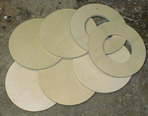
Centering rings and bulk plates
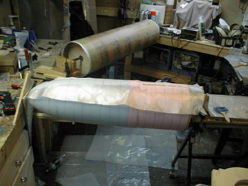
I decided to make the NC out of foam and glass it.
I got some foam from Home Depo that was 2 in thick, this comes in 2x8 foot
sheets.
As you will see in the photos I needed two and a half sheets and used
blue and pink types.
I started by placing the tube on the foam and tracing around it.
I then cut out these pieces using a hand saw.
When all cut out I marked the center of each piece and drilled a 1in hole in each piece.
I put down some wax paper on the floor and placed the first foam piece on
this.
I then mixed up a batch of epoxy and put some in the hole in the foam and on
the end of the 1in dowel.
I proceeded to put epoxy on the dowel and glue on each piece. I put some weight on top and let it dry overnight.

Foam glued to dowel
I cut odd the corners of the foam so it would fit on my lathe.

Foam trimmed down
With the foam trimmed it still would not fit on my lathe. Upon closer inspection I found that 12in is the largest diameter my lathe can support so I had to come up with a way to trim it to almost finish size.
Firstly, the sonotube was actually 11.5in ID so that gave me a bit of room
for error.
It was fairly easy, I made two bulk plates to act as templates and
screwed them to the dowel, then cut it with a hotwire.

Cutting foam to shape with hot
wire

Foam cut to shape
Once cut to shape I mounted it to the lathe and shaped it to look like a nosecone.

Shaping on lathe
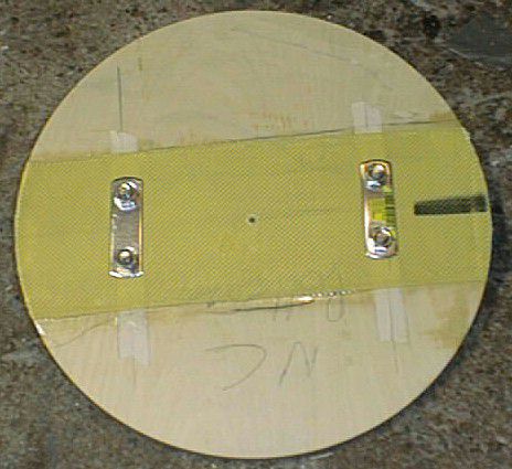
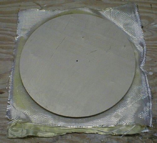
I cut a 1/2in bulk plate that will attach to the bottom of the nosecone and
be glassed in place when the foam is glassed.
I put a strip of 4in wide
kevlar on the backside of this plate to reinforce where the two 5/16in SS
u-bolts will go through.

NC BP with kevlar
NC BP Ubolts mounted
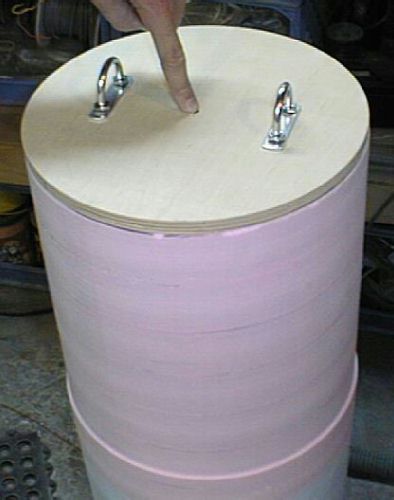
NC BP mounted

NC shaped
I put some paper down and placed the NC on it and traced its shadow onto the paper

Tracing outline

Cutting out glass
Glassing NC

NC glassed

NC bulkplate
I thought about vacuum bagging the fins but decided to do the good ol waxpaper/heavy weight approach.
Fins with CF
Put Kevlar wrap on end of tube
I decided to put a wrap of 4in wide Kevlar tape on the end of the
tube to strengthen the end so it can't zipper.
I pealed a layer off the tube
so there wont be a bump where the Kevlar is.
I then glued it in place with
West Systems epoxy.
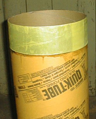
Kevlar epoxied in place
Fiberglass 3 x 48in BT sections
I glassed the tubes on my rotisserie
I used 6oz E-glass that I got off Ebay
I put 3 layers on the first tube

Tube with first layer of glass
The tube on the left has the finish glass on it, you can see it in the photo.

Tubes Glassed
The thrust plate will take the motors thrust and transfer it to the upper section of the rocket.
I cut two bulk plates out of 1/2in plywood and sandwiched them together with 4 layers of 2oz Kevlar cloth and 2 layers of 6oz glass in between them.
Thrust plate before trimming
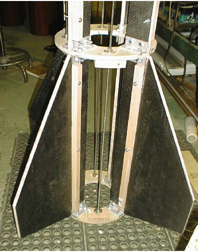
The fincan consists of the four fins, two CR's and the thrust
plate.
The lower section will be assembled with bolts and Aluminum
angle.
The upper section will be 2x3's or 1x2's assembled with bolts and
Aluminum angle.
The 'coupler' at the top, above the TP, will also be made out
of wood but it will be glassed onto the TP.
I will assemble the lower section
first
Here is a photo of the brackets mounted to the CR.
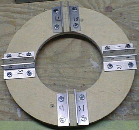
Hardware test fit
I assembled the lower section for a test fit..
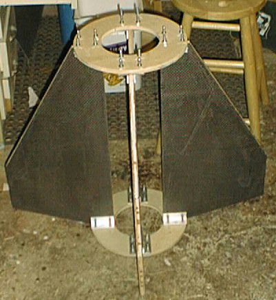
Fins test fit
I assembled the coupler section of the fincan out of 1x2's with 1/2in ply bulk plates on each end.
I glued and fiberglassed this together.
Here it is next to a martini for scale.
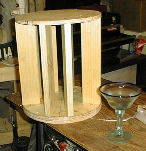
Fin can coupler
I cut the fin slots with my dremel.
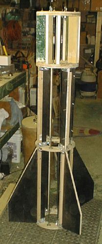
Here is a picture of the body tube in place on the fincan.
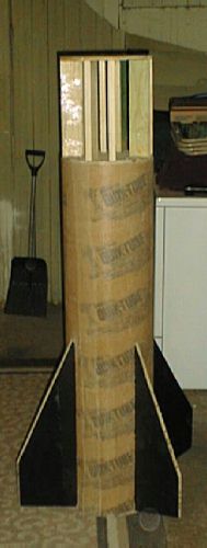
BT in place
I assembled the complete fincan and added oak wood strips for the screws that attach the body to screw into
Fincan bottom section
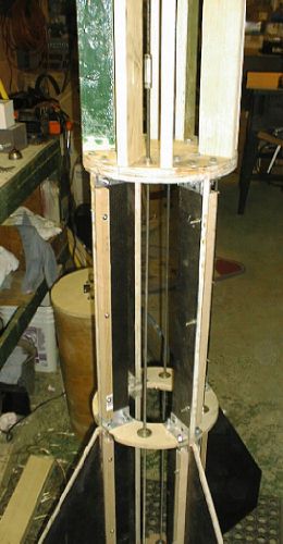
Fincan center section
After I got the fincan together I didn't feel comfortable with the
recovery attachment point on top of the fincan.
It was a single 1/2in plate
with an Al strap.
I added two layers of Kevlar and another 1/2in bulk plate. Because of these mods I had to make the all thread longer. I used coupler nuts to do this. These mods can be seen in the following photo.
Fincan inside view
Ejection charges and NC shear pins
Well I have been giving this allot of thought.
I certainly dont want the NC coming off at apogee, but I also dont want to use too much pressure to push it off.
I am looking at 4 x #4 shear pins. In doing the math with the
figures I found it takes 70# force to break a #4 nylon screw.
Thats 70 *
4 = 280# of force!!
The space inside the tube between the e-bay bulk plate and NC bulk plate is 24in. But wait, I should also count the section of tube that is taken up by the NC shoulder, because before the NC is out, this area is going to increase the internal volume and if not taken into account could cause the NC to come partly off.
For an ejection charge what I will do is start with 300lbf for
testing.
Given the ID of 11in I need 3.2PSI to get 300lbf.
With a length
of 24in it would require 3.7grams of BP and at 36in it would require
5.5grams.
Testing will start with 4grams. But some pressure will be lost to vent holes so 4.5 --> 5g is more likely.
The first flight used 4x#4 shear pins and the charges
used were Drogue=6.75g and Main=8.1g
This amount worked perfectly as the NC
remained attached till it was supposed tocome off at1300'.
Vent holes
Since the flight is planned to 6000' if the pressure change is 1/2PSI / 1000'
thats a difference of 3PSI from ground to apogee.
That's 339lbf. Enough to
break the shear pins and separate the NC.
4in to 6in motor mount adaptor :
The motor for the initial flight is a 4in motor.
To accomodate this motor I made a motor adaptor that is
comprised of 5 centering rings with 3 pieces of all thread holding them in
place.
I installed tee nuts in the forward CR and threaded the rods into it,
I then added the other rings so they hit between and on the two remaining CR's
that hold the fins.
This worked great except that the motor would not slide
all the way in when the rocket was horizontal.
So we had to stand it on end
to load the motor, this was aided by a hay bail that was in the field.