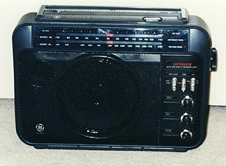
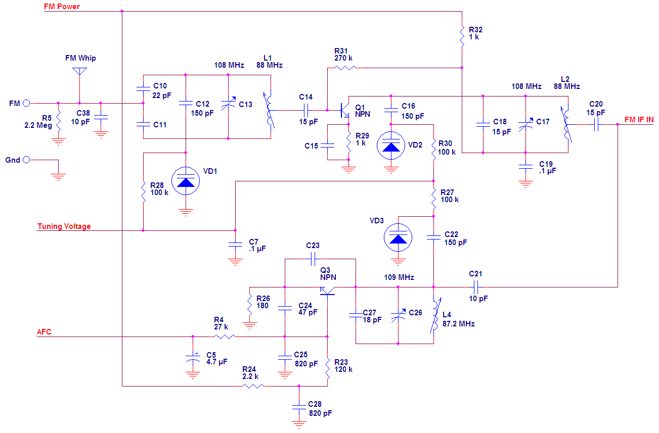
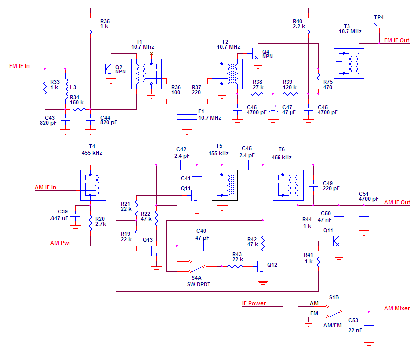
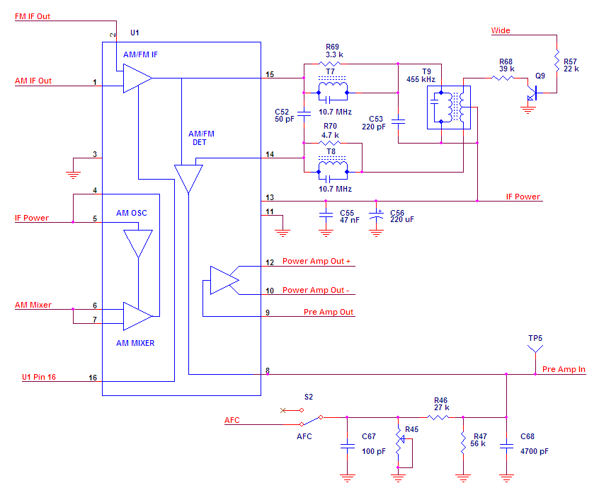
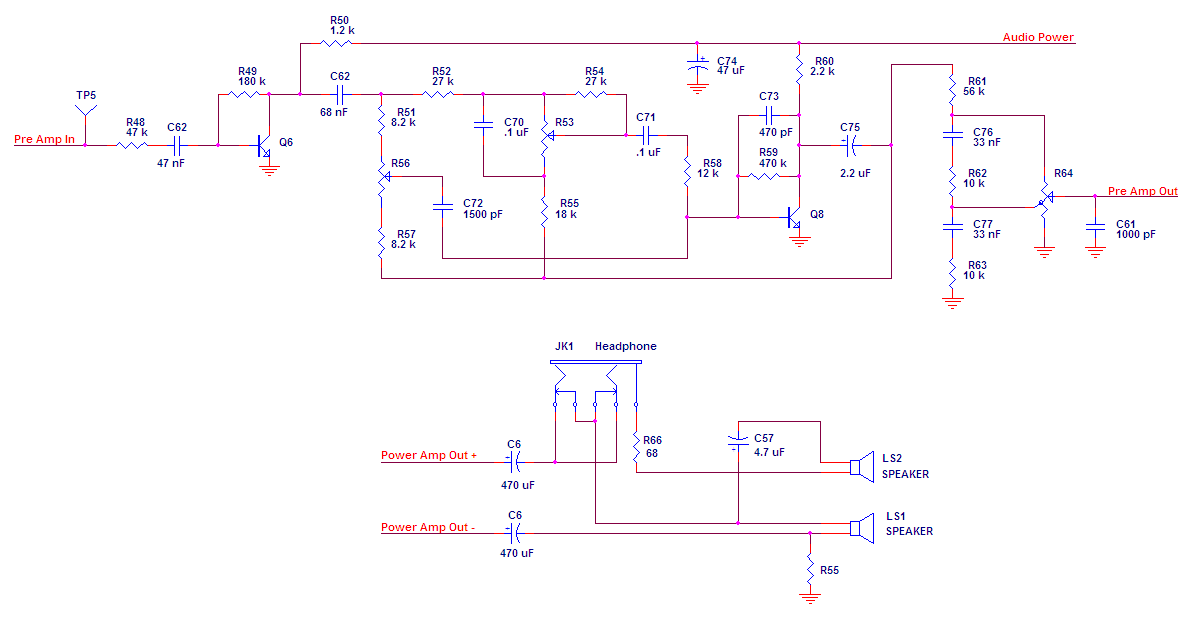
The GE Superradio 3 Tech Page
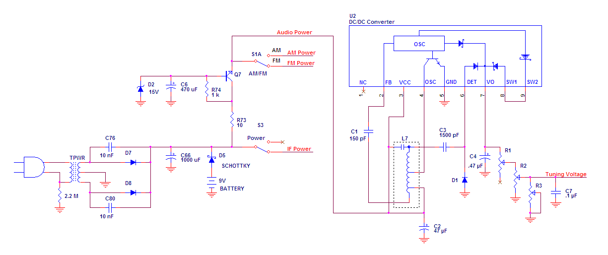
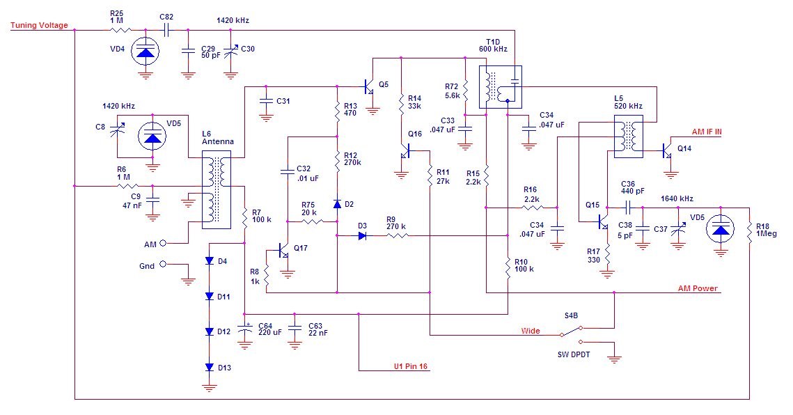
The existing Thompson manual schematic I found on the web is terrible. I have transcribed it the best I can using OrCad Capture. There
was conflicting and missing information on the original, which I resolved the best I could as an experienced Engineer. I found it
particularly hard to discern every "dot" where wires crossed. If you can find any mistakes - PLEASE let me know about them at  !
!
For your convenience (and schematic readability), I have split it into several functional sections:
Internet Explorer fits the graphic to the screen on low screen resolutions. If the schematic is unreadable, be sure to click that zoom thing in the lower right hand corner. Or just right click the graphic to download.
Refer to the graphic below for locations of alignment points. The conventional "coils low" / "caps high" method works well. Don't touch the FM IF and detector unless you know what you are doing. The DC-DC converter coil doesn't need to be adjusted at all if you can tune to the high end of both bands. Don't touch the Tune Low and Tune High pots unless your radio is off by the same amount on both bands. Consult the Thompson Service Manual if you want step by step instructions. If you use the manual, several other people have done diagrams of parts with reference designators.
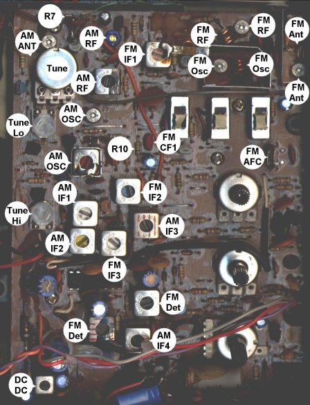
The GE Superradio 3 can benefit from a narrow ceramic filter the same as any other FM radio. Referring to the picture above - the ceramic filter is near the center of the board. The radio comes with a 280 kHz filter installed, any width down to 90 kHz should work. No matching is required.
I discovered - almost by accident - that placing a 47 k resistor in parallel with R7 and R10 narrows AM selectivity and increases sensitivity (of an already hot DX unit). Wide mode response is unaffected, so you can have the best of both worlds. AM selectivity is enhanced to the point that the SR3 is as selective as the SR2. See the picture above for the approximate locations of R7 and R10. A word of caution - tune the dial to the low end and take advantage of the plastic partition above the board - hook the dial string over it to protect it from your soldering iron when soldering R7 - or you may be re-stringing the dial.
I have some information from readers that tell me that newer revisions of SR-3's actually use 47k instead of 100k for R7. Component value changes are almost inevitable over the life of a product, perhaps Thompson saw this page and thought that I had a good idea. I would take it a step further, though, and put a 100k in parallel if you have an R7 that is already 47k.