The GE Superradio 2 Tech Page
The existing Thompson manual schematic I found on the web is terrible. I have transcribed it the best I can using OrCad Capture. There
was conflicting and missing information on the original, which I resolved the best I could as an experienced Engineer. I found it
particularly hard to discern every "dot" where wires crossed. If you can find any mistakes - PLEASE let me know about them at  !
!
The radio is constructed on 2 boards. If you prefer to look at the schematic that way, here it is:
The circuit partitioning on those schematics is not the best for understanding functionality. For your convenience (and schematic readability), I have split it into several functional sections:
Internet Explorer fits the graphic to the screen on low screen resolutions. If the schematic is unreadable, be sure to click that zoom thing in the lower right hand corner. Or just right click the graphic to download.
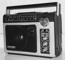
It is easy to disassemble the SR2. All you have to do is remove the knobs remove 6 long screws on each side of the rear case, and one in the battery compartment. The hardest thing to do is to avoid damaging the power switch. It is very easy to bend it to the point where it has mechancial interference from the hole. I have damaged mine that way - the only solution is to use a straight file to make the hole for the switch larger.
The AM band was expanded to 1700 kHz after the SR2 was manufactured. Fortunately, this is still well within the range of alignment. The SR2 circuitry is contained on two main circuit boards, one which contains the tuning capacitor and the other which is roughly IF and audio. With the radio open, the tuning capacitor trim capacitors can be accessed:
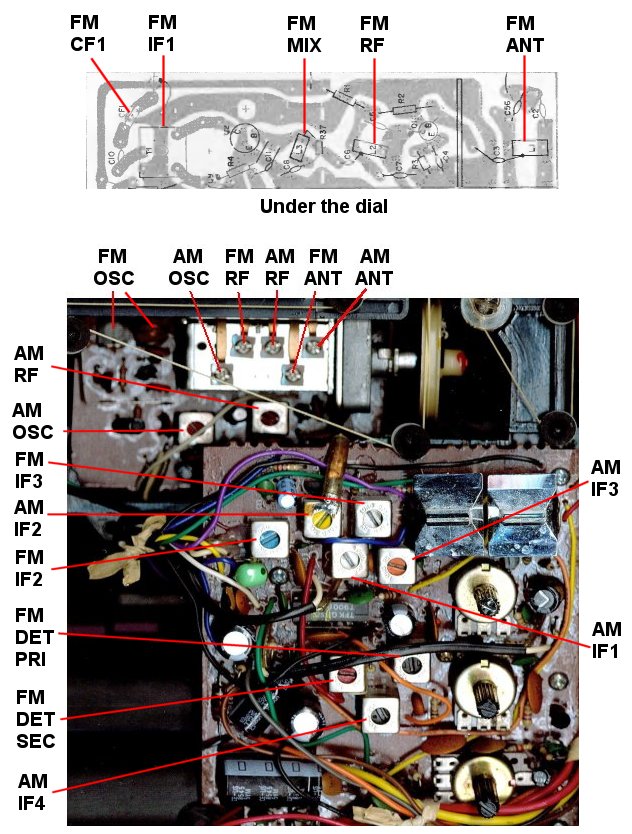
I assume that you know the "caps high / coils low" alignment method. I found that I did not have to worry about the coils to tune the radio where it would receive the expanded band. I adjusted the AM oscillator first, followed by the AM RF and AM antenna. Piece of cake! Just one problem: the dial. I have made this easy for you. I scanned the existing dial, and altered the AM side with Paint Shop Pro to make a new dial. The artwork is below, feel free to snag the graphic:
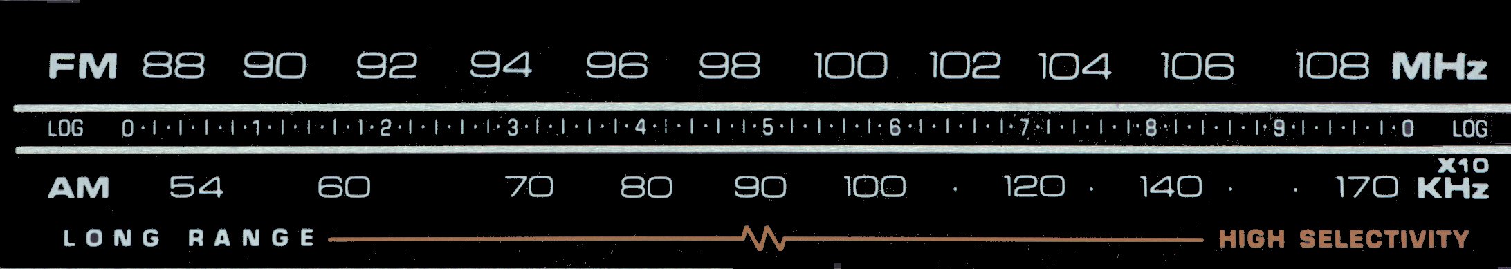
The graphic is actually really BIG, you will have to scale it to fit the radio. I made it really big so small mistakes would disappear when reduced. Except for the fact that now you won't have the cool reflective strip, the new dial legend can be glued directly over the old, and your SR2 will look like it was manufactured for the expanded band.
Just about any FM radio can be improved by swapping the stock 280 kHz ceramic filter for a 150 kHz filter. This is certainly the case with the SR2 On the SR2, the capacitor is located by the 1st FM IF can, which is hidden behind the dial scale in the picture above. It is in the upper left of the board. Be careful of the external AM antenna wires, they are fairly small gauge magnet wire. You don't have to worry about matching, there is only one filter. Since this is a mono radio, you can even use a 110 Khz or 90 Khz filter if have them.
Refer to the graphic above for locations of alignment points. The conventional "coils low" / "caps high" method works well. Don't touch the FM IF and detector unless you know what you are doing. Consult the Thompson Service Manual if you want step by step instructions.