I suppose it is not fair to pick on the projects built by others, but I must make an exception on these two projects because they are so widely copied. They live on the "Single Driver Website" there are two projects that use the "Voigt"pipe design, i.e., the cabinet comes to a point at the closed end. So = 0. Whilerunning simulations withMartin King's Mathcad spreadsheets, in a effort to become familiar with theproperties if quarter-wave pipes, I ran simulations of So = 0 pipes. Finding the "Voigt" pipe to be an undesirable design (See Pipe Behavior 1), I decided to model, build and measure the Herbert Jeschke pipe. That way, I could confirm or deny my suspicions with hard experience. I also modeled the Cain pipe, but did not build one.
I picked these projects because they both use the Radio Shack 40-1354a driver. This is the same drive I used in my Weems' Pipe , Straight Pipe and HT Surrounds.
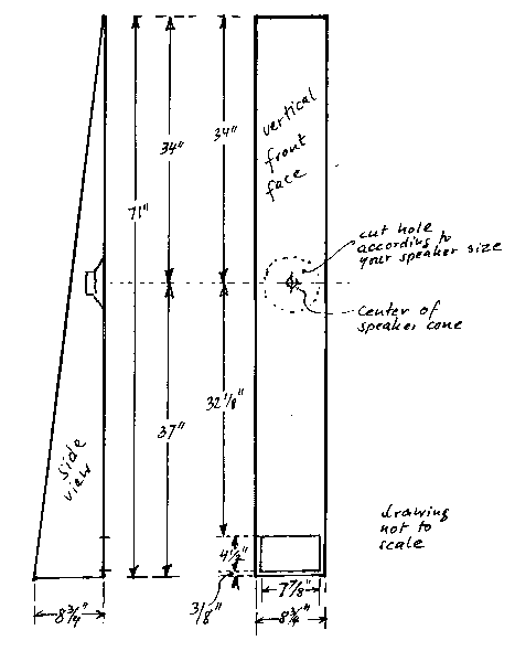
This cabinet was originally designed for the Lowther Club of Norway. I believe that the drawing was taken from that site (no longer available to non-members). It was designed for a Lowther driver, the PM6C, I believe. Jeschke had build the pipes for a undetermined 8" driver, but abandoned the project. He later resurrected the project for the 5 1/4" RS 1354, using a sub-baffle to cover the 8" hole.
I build a test box to the internal dimensions shown on the drawing. I made no effort to finish or pretty it up. I got some 12"x72"x.75" mdf shelving, cut the back to 8.75", and simply screwed the sides to the front and back without further cutting . This jury rig might cause some problems at higher frequencies where diffraction and other things will occur, but are irrelevant at frequencies below 1k hz. It is one heavy box, though.
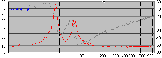
I ran a model simulation using the dimension from the drawing, then took actual measurements, using MLS and 1/16 octave smoothing. The plots with the white background are modeled, the gray, measured. (See note Modeling a So=0 Pipe)
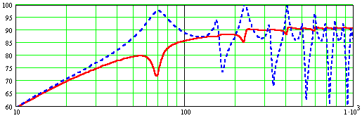

Combined driver and port SPL:
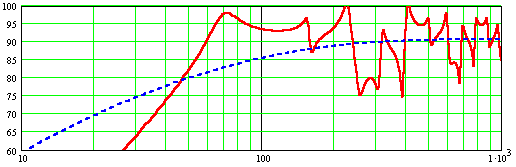
Speaker impedance (with phase):�
Notes:
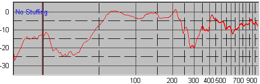
No amount of stuffing could tame the peaks and valleys in this pipe. I ultimately overstuffed the thing and moved the first peak to 80hz and got a smooth decreasing into the hole at 200hz, but nothing that approximates smooth.
Possible modifications:
In an attempt to salvage something out of the project, I increased the throat area to 2"x8.75" and reduced the port to 2"x8.75".
This should give a very listenable speaker with an f3 no higher than 40hz, but it didn't. The sound, no mater how much stuffing, or were placed, was always hollow and boomy.
OK, you want a straight TQWT for aesthetic reasons. Then build this. This design will give decent results.
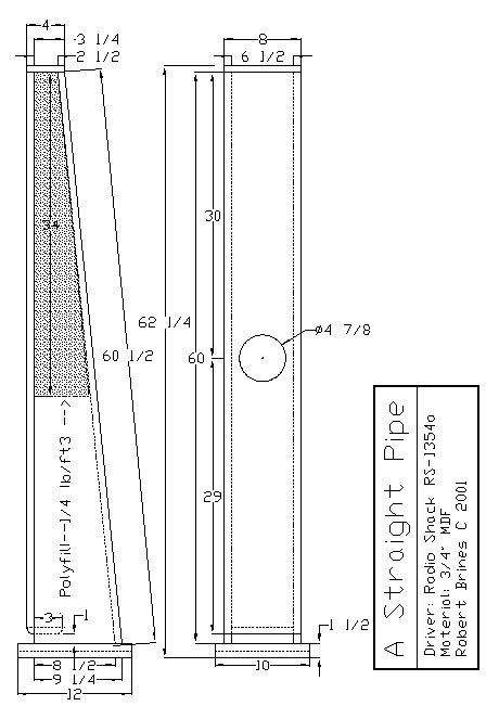
For more details on this design see the Straight Pipe page.
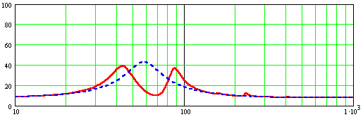
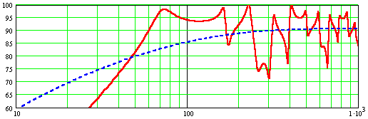
After I built a copy of Herbert Jeschke's pipe and took FR measurements, I compared the results to the model output. While the basic shape of the curves matched, I am used to seeing the details line up better then they did. In partucular, I could not explain the bump in the measured FR at ~125hz, nor could I explain why the measured cut-off is 55hz instead of 70hz.
Modeled output with So ~ 0
Measured output
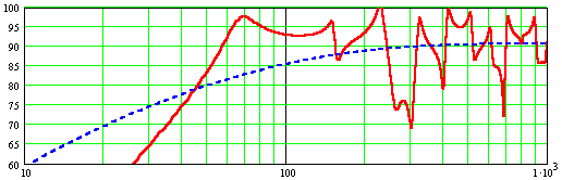
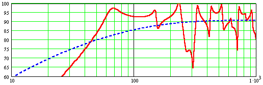
One of the limitations of Martin King's model is that it cannot model So = 0. The equations have a singularity at this point. In layman's terms, the equations blow up at So = 0. To get a plot, I used So = 0.00001 in2. Now, that's arguably pretty close to zero, but not actually zero, so the model is happy. It occurred to me that the actual pipe doesn't work at So = 0 either. To test this hypothesis, I ran a number of simulations, gradually increasing So. The sequence tested was with a throat width of 1/8", 1/4", 1/2" and 3/4". (As the throat width increased, I shortened the pipe to correspond to the new width.)
Throat width = 1/8"
Throat width = 1/4"
Throat width = 1/2"
Throat width = 3/4"
By inspection, The throat with of 1/4" (and pipe length of 70") gives the best agreement with the measured data. This is what I chose to run the comparison with the Jeschke pipe. I am not happy fudging the data, but sometimes real measured data requires adjustment to the model. For reasons explained elsewhere, I would never design a pipe with So=0.