Why a pipe? There are two basic reasons. Because the mid-range frequencies are absorbed by the stuffing and geometry of a pipe, pipes are noted for particularly clear mid-range. The second is to get unusually low bass out of a driver. Back loaded horns are used to force small drivers to produce meaningful bass, even though the driver does not possess the excursion capabilities to do so. This is especially true of ";Full-range"; drivers, which may have an Xmax of a millimeter or less. The problem is that when the pipe unloads, the driver is way beyond Xmax. You have two choices: First, you can assure that the program material never goes below the design cutoff. Otherwise, you will need fairly strong high pass filtering. (If you use ";full-range"; drivers, that kind of goes across the grain, doesn't it?) When the pipe unloads, the excursion is asymptotic to the infinite baffle condition.
Bibliography
Classic Transmission Line (TL)
Mass-Loaded Tapered Quarter-Wave Tube (ML TQWT)
Before you read any farther, read the following references:
Loudspeakers on Damped PipesAugspurger, G. L. :
J. Audio Engineering Society, Vol 48, No. 5, 2000 May
Transmission Lines UpdatedBackman Juha:
Speaker Builder, February, March, April, 2000
A Computational Model of Transmission Line LoudspeakersKing, Martin J. :
Audio Engineering Society Preprint 3326
Transmission Line Theory DerivationThere was a series of articles in SpeakerBuilder Magazine by Augspurger and A. Monk. I don�t have the references, but they provide some filler information to the above references.
Unpublished
Ok, good! We are now on common ground. Everything that follows in my take on the references above, internet postings (in particular, Full-Range Driver Forum and High Efficiency Speakers at AudioAsylum.com) and my own limited experience.
Glossary To avoid the cumbersome term ";quarter-wave resonator";, I will call this class of cabinet a ";pipe";. Pipes are an interesting class of speaker cabinets. All three authors quoted above demonstrate that pipes are a subset of horn enclosures, more specifically, constant taper horns. They also demonstrate that the vented box cabinet is a subset of horn! True horns are designed to avoid resonance at operating frequencies. Pipes are designed to resonate strongly at the design frequency.There are several terms used to categorize pipes. These are general use terms, and do not necessary reflect technical characteristics:
Pipe parameters are";
To give you an idea of what to expect from quarter-wave tubes, I present the following: (The graphs were produced by Martin J King's Mathcad model cited above. The cases are not optimized. The driver is the Fostex FE164, the cross section area is 3 time the driver area and the pipe is 60"; long. The port, or mouth, is equal to the pipe cross-section.)
This is the standard TL. The pipe is not tapered, and the driver is at the closed end of the pipe.
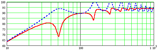
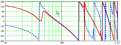
The driver and port output looks like this: (The red is the driver, the blue line is the port)
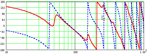
The driver and port phase is:
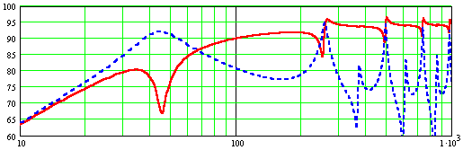
Finally, the combined output is: (The red line is the TL combined output, the blue line an infinite baffle)
The driver response in a pipe follows the response of the driver mounted on an infinite baffle. The difference is that energy is taken from the driver at pipe resonance points. Therefore, the dips in the driver FR correspond exactly to to the peaks in the port FR. Since this is a closed pipe, only odd harmonics are present. At each resonate frequency, the pipe suppresses the output of the driver. In between the resonant peaks, the pipe supplies horn loading to the system, i.e., the port output does not return to zero between harmonics. The summation depends upon the relative phase of the pipe and driver. As seen on the second graph, the pipe is alternately in and out of phase with the driver. This caused the classic ";lumpy"; bass (technically, a comb filter) associated with poorly designed pipes.
IN MY OPINION: There is no reason to use a classic TL design. Using the mass-loading technique, with a taper ratio in excess of 4, you can go lower, smoother than a TL. You also maintain the pipe's ability to eat the back wave in the mid range, which gives you that open pure sound that is the reason to use a TL in the first place. An exception is for a bass TL that will be crossed over at or before the first dip. Then, an un-stuffed pipe, as large as you can stand is the way to go.
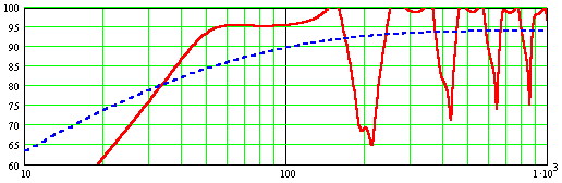
Let's look at what is happening in a ML TQWT. These simulations where run for the Fostex FE164. For the first set of graphs, I chose parameters that produced a dead flat combined frequency response out to 250hz. These are not the parameters I would choose for an actual project, but they provide a very clean look at what is happening in the pipe.
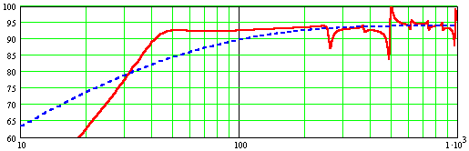
In this simulation, the driver has been moved down the pipe to exactly 0.517 times the pipe length. This almost completely eliminates the resonance at F3. Note a very small wiggle in the port FR at 150hz. That's F3. F7, F9 and F11 are there, but reduced.
The resonant frequency of the driver is not reflected in the output. The only importance of Fs is that Fs determines, along with Qts, the shape of the driver roll-off. As long as the driver output fills in correctly between F1 and F5, Fs is not a consideration. The pipe F1 is typically 1/2-2/3 octave below Fs.
Let's look at the phase graph. Below F1, the driver and port are in quadrature, i.e., 90 degrees out of phase. From F1 to F5 they are in phase from F1 to F5. The driver and port are alternately in and out phase.
So, what are we looking for? If the driver is ideal, and the geometry correct the following will happen: Below F1, the driver and port combine to rise at 24db/octave. The FR curve peaks at F1 at the same db level as the driver at 1000hz. Between F1 and F5, the port output decreases at a rate complementary to the the rise in the driver output. The result is a flat FR between F1 and F5. Beyond F5, the peaks and valleys are small enough to be damped with stuffing:
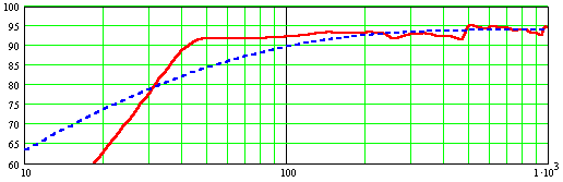
A word on driver suitability. The driver is going to behave as if on an infinite baffle, disregarding the nulls at pipe resonance. The pipe resonance at F1 has an ultimate roll-off at the low end of 12db/octave and the upper roll-off determined by cross-sectional area -- the larger the area, the sharper the roll-off. A low Q driver will have a shallow slope and low output at F1. A high Q driver will have a steeper slope, but higher output at F1. (This assumes that F1 is near the driver fs.) Bottom line: Low Q drivers will have a deeper sag between F1 and F5. High Vas drivers will have a sloped output favoring high frequencies. A high Vas driver will sag at the bottom, a low Vas driver will show a peak at F1. Choose a driver with a Qts of .3-.5 (perhaps higher, I have no experience here) favoring the high end. Avoid a high Vas driver. Most modern drivers are OK for Vas.
After playing with the Mathcad worksheets for a while, and after building a few pipes, I offer some guidelines: