(Red=Summed FR, Blue=Infinite baffle response)
Driver and Port Frequency Response

(Red=Driver, Blue=Port)
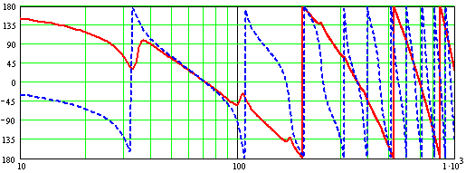
Driver and Port Phase

(Red=Driver, Blue=Port)
Impedance Response

(Red=Summed, Blue= Driver of IB)
A TL is made up of a driver that is a 2nd-order high-pass filter and a pipe that acts as a series of 2nd-order band-pass filters. The combination creates a 4th-order high-pass system. To illustrate this, I present three graphs created by Martin King�s MathCad worksheets. The driver used for these examples is the 7� Peerless 850122. The specs for this driver are shown on the Peerless Pipe page.
The first illustration is for a 90� pipe with a constant 10 �� diameter, the driver mounted in the closed end of the pipe. I chose the dimensions of the pipe for this example to clearly show the features of the harmonic series in a quarter-wave pipe. The pipe is long enough to place the pipe resonance well removed from the driver resonance. The pipe cross-sectional area is large enough that end effects, which are so important in designing quarter-wave resonators, are minimal.

(Red=Summed FR, Blue=Infinite baffle response)
Driver and Port Frequency Response

(Red=Driver, Blue=Port)
Driver and Port Phase

(Red=Driver, Blue=Port)
Impedance Response

(Red=Summed, Blue= Driver of IB)
The driver resonance is completely suppressed in the frequency response, although it shows up well in the impedance graph. At each pipe harmonic, the driver output is suppressed, showing in both the frequency response and the impedance.
So, this is what we have to work with. A simple stopped pipe is a wildly spiky thing. The driver response is essentially out of the hands of the designer. The art of TL design is to adjust the resonant frequency and the Q of the pipe, and to suppress all harmonics above the fundamental frequency of the pipe.
Pipe Length and cross-sectional area:
The most obvious means of adjusting the pipe resonant frequency is to change the length of the pipe. Making the pipe longer lowers the resonant frequency, and I�m not going to demonstrate that fact. I chose 60� for this example, not because that is the resonant frequency of the driver (pure serendipity), but because I know that it leads to a good design. This length is arrived at by experimentation.
What is less obvious is that the output of the pipe increases with increasing cross-sectional area. Increasing the pipe area also increases the pipe Q. For this example I will start with the area of the pipe equal to the Sd of the driver:
Combined Response

Driver/Port Response

Area=2*Sd
Combined Response

Driver/Port Response

Area=4*Sd
Combined Response

Driver/Port Response

Inductive loading (Mass Loading):
The resonant frequency of a pipe depends two things, the length of the pipe and the acoustical impedance within and at the end of the pipe. If the impedance is capacitive, the pipe will be longer than calculated by f = c/4L, and if the impedance is inductive, the pipe will be shorter than calculated. The electrical analog is the base-loaded quarter-wave radio antenna. The coil at the base of the antenna shortens physical length for a given resonant frequency. The same applies to quarter-wave pipes.
The easiest ways to increase inductive impedance of a pipe is to either taper the pipe or to reduce the area and increase the length of the port. Port geometry will be discussed later with the discussion of straight pipes and TQWT�s. Here, I will increase the taper ratio by decreasing the port area. The pipe has a constant taper ratio throughout. �The first pipe in this series it the previous example of a straight pipe with area = 4*Sd
Combined Response

Driver/Port Response

Taper ratio = 4 to 1
Combined Response

Driver/Port Response

Taper ratio = 8 to 1
Combined Response

Driver/Port Response

Driver Position:
It is unlikely that a real speaker cabinet would have the driver built into the closed end of the pipe. There are special cases that warrant this but that is off topic here. The position of the driver on the baffle will be determined by construction restraints, diffraction considerations and esthetic considerations. However, if possible, the driver should be placed so as to cancel one of the pipe harmonics. Placing the driver 1/3rd of the length down a straight or tapered pipe will cancel the 1st overtone, the 3rd harmonic, 1/6th down will cancel the 2nd overtone, the 5th harmonic:

1/3rd Down

1/6th Down

The fundamental standing wave in a stopped pipe has a zero velocity, high pressure node at the closed end, and a high velocity, low pressure anti-node at the open end. Higher harmonics have additional nodes and anti-nodes distributed throughout the pipe. The stuffing must be placed in the pipe in such a way as to affect higher frequencies while leaving low frequencies untouched. By placing the stuffing in the closed end of the pipe, the high velocity anti-nodes of the harmonics will be in the stuffing, while only the low velocity portion of the fundamental will be in the stuffing. Taking the last example above and placing 1 lb/ft3 in the upper quarter of the pipe:

Wool has long been considered the best stuffing for quarter-wave pipes. However, experimentation shows that there is nothing magical about wool. Polyfil�, Fiberglas and Miraflex� all have about the same characteristics and are one-for-one replaceable by weight/volume. I prefer Polyfil� for ease of use. It usually packs down tight enough to stay in place. Miraflex� tends to mat and Fiberglas� can be ugly if gloves and mask are not warn.