HOW TO BUILD AN OPTICAL ENCODER INSIDE A SERVO
by Charley Loomis
This is just a web page I threw together quickly to show how I included
a simple optical encoder in a servo modified for robotics. What this means
is to be able to keep track of how far the output shaft of a R/C servo
has turned, by generating pulses as the shaft turns, and feeding those
pulses to a microcontroller. The servo I show here generates 11 pulses
per revolution, not alot, but with the 4" Dia. wheels I am using, thats
approximately 1 pulse per inch. To learn how to modify an R/C servo for
continuos rotation go to KevinRoss's
page. Kevin's page is clear and very simple. I am using Hitec Servos,
and they are a bit more difficult to modify, everything is the same except
that you have to dismantle the Pot in a Hitec servo.Email
me if you would like me to add how to modify the pot in a Hitec servo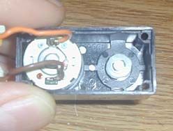 .I
also installed a 5K Trim Pot instead of the fixed resistors Kevin uses.
This allows for better fine tuning of the servo. I didn't attempt to teach
anybody about electronics, there are hundreds of good sites out there that
can do that way better than I could. This page just mainly shows the mechanical
modification, but you can contact me with any questions and I will be glad
to answer them.
.I
also installed a 5K Trim Pot instead of the fixed resistors Kevin uses.
This allows for better fine tuning of the servo. I didn't attempt to teach
anybody about electronics, there are hundreds of good sites out there that
can do that way better than I could. This page just mainly shows the mechanical
modification, but you can contact me with any questions and I will be glad
to answer them.
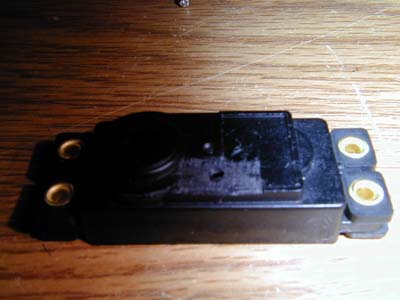
This is a before and after picture. 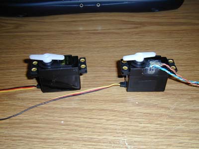 Ok,I
know it's not completely inside the servo, but the wires have to come out
somewhere. I still think it looks better than a striped piece of paper
on the inside of a wheel. But then this method only gives you 11 positions
per revolution, where as most encoders give 25-100 positions, I guess it
all depends on how tight your navigation needs are.
Ok,I
know it's not completely inside the servo, but the wires have to come out
somewhere. I still think it looks better than a striped piece of paper
on the inside of a wheel. But then this method only gives you 11 positions
per revolution, where as most encoders give 25-100 positions, I guess it
all depends on how tight your navigation needs are.
The first step is to take the servo apart, if you
modified your servo yourself, you should be familiar with this part. Remove
the four long screws in the back of the servo and remove the gear train
cover. Have a nice long look at the gears and cover, they'll never look
the same again. 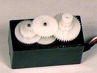 See
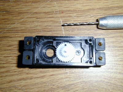
the gear in the middle, that's what will be the stator for the encoder.Lift
the middle gear out, lay it flat side down on the work bench, get a 1/16"
drill bit and drill a hole in it. Ok, lets be a little clearer on this,
don't use a power drill, I use a pen vise, you can do it with just a drill
bit only. Be patient and take your time. You want the hole near the outside
of the gear, but not too close or you will ruin the gear. Yes,drilling
holes in the gear will weaken it, but there is always a down side in life.
See
the gear in the middle, that's what will be the stator for the encoder.Lift
the middle gear out, lay it flat side down on the work bench, get a 1/16"
drill bit and drill a hole in it. Ok, lets be a little clearer on this,
don't use a power drill, I use a pen vise, you can do it with just a drill
bit only. Be patient and take your time. You want the hole near the outside
of the gear, but not too close or you will ruin the gear. Yes,drilling
holes in the gear will weaken it, but there is always a down side in life.
 The
next step is to remove the pin that the middle gear was on, just gently
wiggle it and pull it out of the gear train. Now put it in it's prospective
place in the top cover. Slide the gear you just drilled the hole in onto
the pin, flat side first. Line up the hole like it is in the photo. It
is very important to line the hole up like it is in the picture. It must
be as close to the outside of the cover as possible, otherwise the detector
will not be able to line up with the emitter. When your happy with the
alignment, slide your 1/16" drill bit through the hole in the gear and
drill through the top of the cover. Don't worry, we haven't gotten to the
big hole yet, that's when it gets really fun. After you drilled through
the top of the cover flip the cover over and look at the top.
The
next step is to remove the pin that the middle gear was on, just gently
wiggle it and pull it out of the gear train. Now put it in it's prospective
place in the top cover. Slide the gear you just drilled the hole in onto
the pin, flat side first. Line up the hole like it is in the photo. It
is very important to line the hole up like it is in the picture. It must
be as close to the outside of the cover as possible, otherwise the detector
will not be able to line up with the emitter. When your happy with the
alignment, slide your 1/16" drill bit through the hole in the gear and
drill through the top of the cover. Don't worry, we haven't gotten to the
big hole yet, that's when it gets really fun. After you drilled through
the top of the cover flip the cover over and look at the top.
 You
will have to remove the name plate from the cover, and shave off the little
edge around the name plate with an E-xato knife. Please be careful, if
you slip and cut yourself you will bleed to death, and I get your stuff.Sand
around the little hole you made, this will roughen the surface a bit and
allow the hot glue a place to stick. Look at the picture and you might
be able to tell what I am talking about.
You
will have to remove the name plate from the cover, and shave off the little
edge around the name plate with an E-xato knife. Please be careful, if
you slip and cut yourself you will bleed to death, and I get your stuff.Sand
around the little hole you made, this will roughen the surface a bit and
allow the hot glue a place to stick. Look at the picture and you might
be able to tell what I am talking about.
Ok, now comes the best part. With the gear still
in the cover you need to drill a hole in the side. The hole needs to be
in line with the pin in the center of the cover, directly over the hole
you drilled in the top. It's hard to explain exactly where this hole needs
to be but if you look at the photos and understand what you are making
you will figure it out. The hole in the side of the case needs to be enlarged
so the detector to fit snugly inside the hole.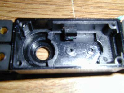 This
photo shows the detector poking in through the side of the case. The gear
needs to spin freely between the detector and the top of the cover. Again,
I used an E-xacto knife to enlarge the hole, remember, I get your stuff
if your not careful. Also roughen the surface around the outside of this
hole as well.
This
photo shows the detector poking in through the side of the case. The gear
needs to spin freely between the detector and the top of the cover. Again,
I used an E-xacto knife to enlarge the hole, remember, I get your stuff
if your not careful. Also roughen the surface around the outside of this
hole as well.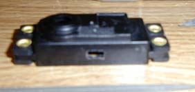
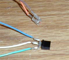
Ok, the sensors, I robbed them out of a mouse, I guess you could buy
them as well, doesn't really matter how you get them. The little clear
one is the emitter, and the black one is the detector. Solder some small
wires to the pins, I used the wire from the cord of the mouse, even better
if you use some small shielded wire, like what you can find inside old
VCRs.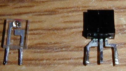 Oh
yea, make sure you keep track of which side of the detector faces the emitter,
otherwise you will have to cut through the hot glue and remove the detector
and flip it over, Not that I had to do anything like that before *sic*.
With the gear and pin in place in the cover, slide the detector through
the hole in the side.
Oh
yea, make sure you keep track of which side of the detector faces the emitter,
otherwise you will have to cut through the hot glue and remove the detector
and flip it over, Not that I had to do anything like that before *sic*.
With the gear and pin in place in the cover, slide the detector through
the hole in the side. 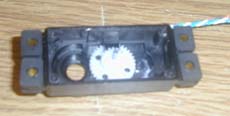 You
want it in as far as it can go without touching the gear. When I put mine
together I place a small piece of paper between the gear and the detector.When
it is in place, hot glue it into position from the outside of the case.
(Why use hot glue and not Epoxy? Remember what I said about putting it
in upside down?) When the glue cools, remove the piece of paper and make
sure the gear spins freely. The emitters I used have a tiny bump on their
face that fit nicely into the hole in the top of the case, just make sure
they are lined up, and hot glue them down.
You
want it in as far as it can go without touching the gear. When I put mine
together I place a small piece of paper between the gear and the detector.When
it is in place, hot glue it into position from the outside of the case.
(Why use hot glue and not Epoxy? Remember what I said about putting it
in upside down?) When the glue cools, remove the piece of paper and make
sure the gear spins freely. The emitters I used have a tiny bump on their
face that fit nicely into the hole in the top of the case, just make sure
they are lined up, and hot glue them down.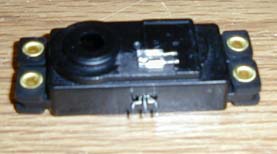
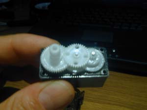
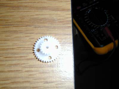 Almost
done, You need to drill some more holes in the gear, the more you drill,the
more pulses out per revolution, and the weaker your gear gets. I use four,
I wouldn't recommend more than six. You will have to enlarge the holes
a bit, sorry, but that's life, nothings perfect. Again, be careful,go very
slowly, I use and E-xacto knife for this to, I sure hope you have some
cool stuff.
Almost
done, You need to drill some more holes in the gear, the more you drill,the
more pulses out per revolution, and the weaker your gear gets. I use four,
I wouldn't recommend more than six. You will have to enlarge the holes
a bit, sorry, but that's life, nothings perfect. Again, be careful,go very
slowly, I use and E-xacto knife for this to, I sure hope you have some
cool stuff.
When you put the servo together you have to put
the pin and the gear with the holes in the top of the case first. Make
sure everything lines up, and be gentle, if you have to force it, it's
not right. That's it, your servo now has a built in encoder.
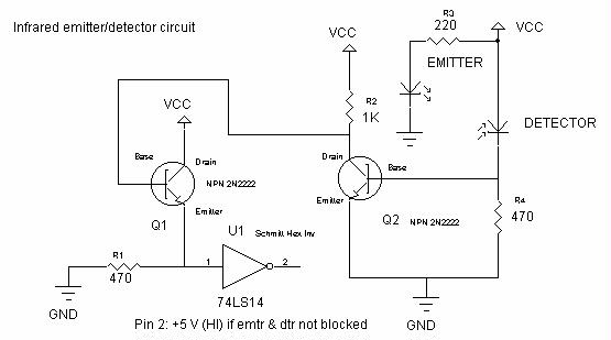
I tie both of the outside pins of the detector together because you
cant line the detector up perfectly with the hole in the gear, and this
gives the strongest signal. The center pin goes to positive.
This is the circuit I use for my encoder, I changed both of the 470ohm
resistors to 1K ohms, and the emitter resistor to 330 ohms.
If anybody has a better circuit please let
me know. I'm very interested in ways to improve this idea, it works
very well but it takes a bit of adjusting.