A silicon-controlled rectifier (or semiconductor-controlled rectifier) is a 4-layer solid state device that controls current flow. The name "silicon controlled rectifier" or SCR is General Electric's trade name for a type of thyristor. The SCR was developed by a team of power engineers led by Gordon Hall and commercialised by Frank W. "Bill" Gutzwiller in 1957.
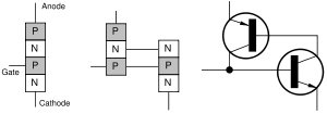
An SCR can be seen as a conventional rectifier controlled by a logic gate signal. It is a 4-layered, 3-terminal device. A p-type layer acts as an anode and an n-type layer as a cathode; the p-type layer closer to the n-type(cathode) acts as a gate.
In the normal "off" state, the device restricts current flow to the leakage current. When the gate to cathode voltage exceeds a certain threshold, the device turns "on" and conducts current. The device will remain in the "on" state even after gate current is removed so long as current through the device remains above the holding current. Once current falls below the holding current for an appropriate period of time, the device will switch off.
If the applied voltage increases rapidly enough, capacitive coupling may induce enough charge into the gate to trigger the device into the "on" state; this is referred to as "dv/dt triggering." This is usually prevented by limiting the rate of voltage rise across the device, perhaps by using a snubber. "dv/dt triggering" may not switch the SCR into full conduction rapidly and the partially-triggered SCR may dissipate more power than is usual, possibly harming the device.
SCRs can also be triggered by increasing the forward voltage beyond their rated breakdown voltage (also called as breakover voltage), but again, this does not rapidly switch the entire device into conduction and so may be harmful so this mode of operation is also usually avoided. Also, the actual breakdown voltage may be substantially higher than the rated breakdown voltage, so the exact trigger point will vary from device to device.
SCRs are made with voltage ratings of up to 7500 volts, and with current ratings up to 3000 RMS amperes per device. Some of the larger ones can take over 50 kA in single-pulse operation. SCRs are used in power switching, phase control, chopper, battery chargers, and inverter circuits. Industrially they are applied to produce variable DC voltages for motors (from a few to several thousand HP) from AC line voltage. They control the bulk of the dimmers used in stage lighting, and can also be used in some electric vehicles to modulate the working voltage in a Jacobson circuit. Another common application is phase control circuits used with inductive loads. SCRs can also be found in welding power supplies where they are used to maintain a constant output current or voltage. Large silicon-controlled rectifer assemblies with many individual devices connected in series are used in high-voltage DC converter stations.
Two SCRs in "inverse parallel" are often used in place of a TRIAC for switching inductive loads on AC circuits. Because each SCR only conducts for half of the power cycle and is reverse-biased for the other half-cycle, turn-off of the SCRs is assured. By comparison, the TRIAC is capable of conducting current in both directions and assuring that it switches off during the brief zero-crossing of current flow can be difficult.
Typical electrostatic discharge (ESD) protection structures in integrated circuits produce a parasitic SCR. This SCR is undesired; if by accident it is triggered, then the IC will go into latchup and may be destroyed.
Back