 |
|
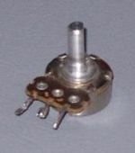
Potentiometer
 |
A potentiometer is a variable tapped resistor that can be used as a voltage divider.
A form of potentiometer is used as an instrument to measure the potential (or voltage) in a circuit by tapping off a fraction of a known voltage from a resistive slide wire and comparing it with the unknown voltage by means of a galvanometer. The sliding tap of the potentiometer is adjusted and the galvanometer briefly connected to both the sliding tap and the unknown potential; the deflection of the galvanometer is observed and the sliding tap adjusted until the galvanometer no longer deflects. At that point the galvanometer is drawing no current from the unknown source, and the magnitude of voltage can be calculated from the position of the sliding contact. This null balance method is a fundamental technique of electrical metrology.
As an electrical component, potentiometer (or 'pot' for short) describes a three-terminal resistor with a sliding contact that forms an adjustable voltage divider. If all three terminals are used, it can act as a variable voltage divider. If only two terminals are used (one side and the wiper), it acts as a variable resistor or rheostat. Potentiometers are commonly used as controls for electrical devices such as a volume control of a radio. Potentiometers operated by a mechanism can be used as position transducers, for example, in a joystick.
Potentiometer as measuring instrument
Before the introduction of the calibratable (sprung) moving coil meter, potentiometers were used in measuring voltage, hence the '-meter' part of their name. Today this method is confined to standards work, and is not normally used in other areas of electronics.
The original potentiometer is a type of bridge circuit for measuring voltages by comparison between a small fraction of the voltage which could be precisely measured, then balancing the two circuits to get null current flow which could be precisely measured. The word itself derives from the phrase "voltage potential," and "potential" was used to refer to "strength." The original potentiometers are divided into four main classes listed below:
1) Constant current potentiometer
This is used for measuring voltages below 1.5 volts. In this circuit, the unknown voltage is connected across a section of resistance wire the ends of which are connected to a standard electrochemical cell that provides a constant current through the wire, The unknown emf, in series with a galvanometer, is then connected across a variable-length section of the resistance wire using a sliding contact(s). The sliding contact is moved until no current flows into or out of the standard cell, as indicated by a galvanometer in series with the unknown emf. The voltage across the selected section of wire is then equal to the unknown voltage. All that remains is to calculate the unknown voltage from the current and the fraction of the length of the resistance wire that was connected to the unknown emf. The galvanometer does not need to be calibrated, as its only function is to read zero. When the galvanometer reads zero, no current is drawn from the unknown electromotive force and so the reading is independent of the source's internal resistance.
Because the resistance wire can be made very uniform in cross-section and resistivity, and the position of the wiper can be measured easily, this method can be analyzed to accurately determine the uncertainties in the measurement. When measuring potentials larger than that produced by a standard cell, an external voltage divider is used to scale the measured voltage down to approximately 1 volt for measurement by the potentiometer; the uncertainties due to the voltage divider construction and the load placed on the source by the voltage divider then become part of the uncertainty of the overall measurement.
2) Constant resistance potentiometer
The constant resistance potentiometer is a variation of the basic idea in which a variable current is fed through a fixed resistor. These are used primarily for measurements in the millivolt and microvolt range.
3) Microvolt potentiometer
This is a form of the constant resistance potentiometer described above but designed to minimize the effects of contact resistance and thermal emf. This equipment is satisfactorily used down to readings of 1000 nV or so.
4) Thermocouple potentiometer
Another development of the standard types was the 'thermocouple potentiometer' especially modified for performing temperature measurements with thermocouples. Potentiometers for use with thermocouples also measure the temperature at which the thermocouple wires are connected, so that cold-junction compensation may be applied to correct the apparent measured EMF to the standard cold-junction temperature of 0 degrees C.
Potentiometer as electronic component
A potentiometer is a potential divider, a three terminal resistor where the position of the sliding connection is user adjustable via a knob or slider. Potentiometers are sometimes provided with one or more switches mounted on the same shaft. For instance, when attached to a volume control, the knob can also function as an on/off switch at the lowest volume.
Ordinarily potentiometers are rarely used to directly control anything of significant power (more than a watt). Instead they are used to adjust the level of analog signals (e.g. volume controls on audio equipment), and as control inputs for electronic circuits. For example, a light dimmer uses a potentiometer to control the switching of a triac and so indirectly control the brightness of lamps.
Construction of potentiometers
A potentiometer is constructed using a flat semi-circular graphite resistive element, with a sliding contact (wiper). The wiper is connected through another sliding contact to the third terminal. On panel pots, the wiper is usually the centre terminal. For single turn pots, this wiper typically travels just under one revolution around the contact. 'Multiturn' potentiometers also exist, where the resistor element may be helical and the wiper may move 10, 20, or more complete revolutions. Besides graphite, other materials may be used to make the resistive element. These may be resistance wire, or carbon particles in plastic, or a ceramic/metal mixture called cermet.
One form of rotary potentiometer is called a string pot. It is a multi-turn potentiometer with an attached reel of wire turning against a spring. It is convenient for measuring movement and therefore acts as a position transducer.
In a linear slider pot, a sliding control is provided instead of a dial control. The word linear also describes the geometry of the resistive element which is a rectangular strip, not semi-circular as in a rotary potentiometer. Because of the large opening for the wiper and knob, this type of pot has a greater potential for getting contaminated.
Potentiometers can be obtained with either linear or logarithmic laws (or "tapers").
Back