![[MWA Engineering Dept.]](circuitheader.gif)
![[MWA Engineering Dept.]](circuitheader.gif)
A carrier current transmitter injects its signal into the power lines rather than radiating from an antenna. Receivers located near the power lines, and especially receivers plugged into the power lines, can pick up the signal. Carrier current systems were used on many college campuses during the period 1940-1990. They are still legal on US college campuses but the number of carrier current systems in use is declining due to multiple factors.
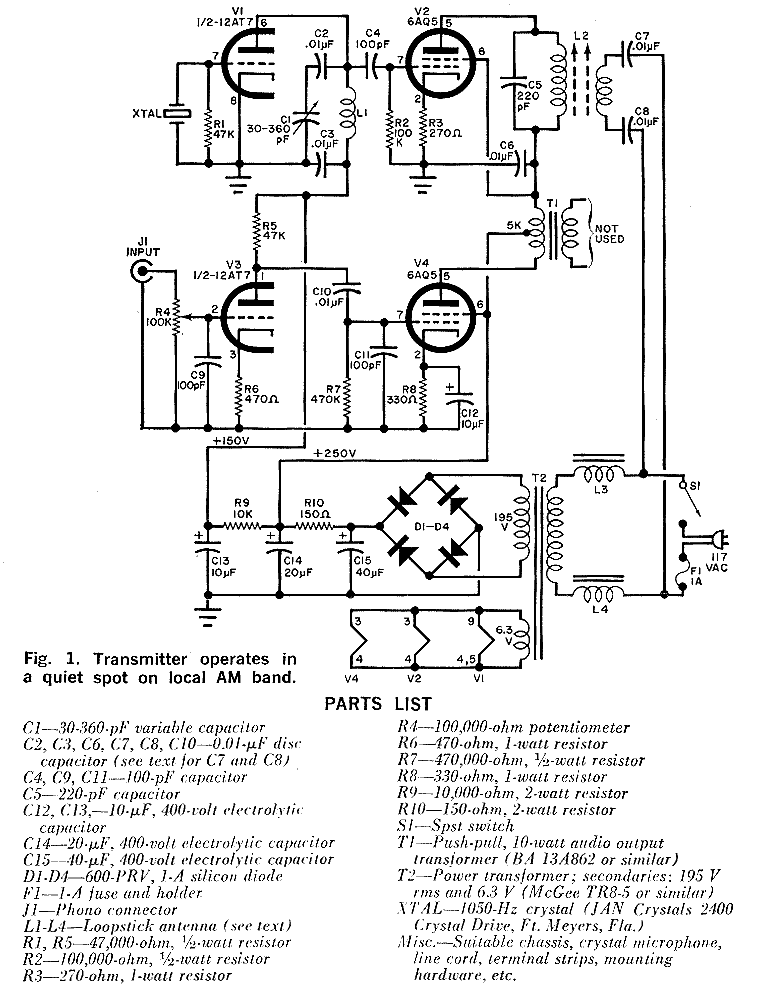
This 5 watt AM carrier current broadcast transmitter was designed by Dr. Jim S. Harmon and published in the seventies. I have not built this, and I think the days when anyone would go to the trouble of building a multi-tube circuit just to get a carrier current transmitter are over, but this design is educational as far as showing 1) how Heising modulation works, 2) how to get 5 watts of RF with readily available parts, 3) one way to couple an AM transmitter's output to the power lines.

Use high-voltage disc caps for C7 and C8 (rated for at least 400 V). L1 thru L4 are loopstick antenna coils (1973 Radio Shack #270-376; you can get similar items now from Antique Electronic Supply at www.tubesandmore.com) L1 and L2 should be several inches apart and at right angles to each other. For a frequency in the 1000 to 1100 kHz range, remove the slug from L1; leave the slug in L2 but remove 55 turns of wire. The output coupling on L2 consists of 21 turns of fine insulated wire wrapped around the inductor. L3 and L4 are unmodified loopsticks. Maybe it would be easier just to make some simple toroidal transformers?
Tune up: Adjust C1 and L2's slug for maximum output. Use an oscilloscope to adjust the input level (R4) for best modulation.
It looks like the ground side of J1 and all the connected parts should go to ground, but perhaps I am mistaken...