![[MWA Engineering Dept.]](circuitheader.gif)
![[MWA Engineering Dept.]](circuitheader.gif)
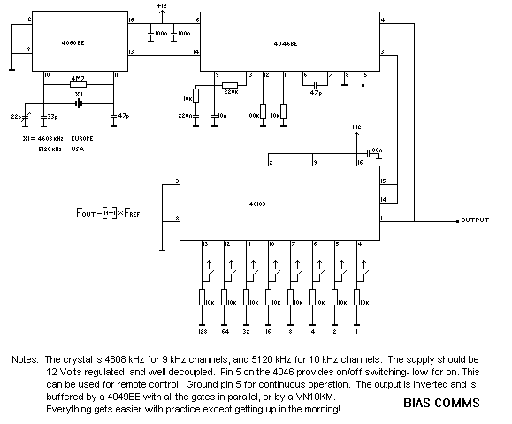
From the good folks at BiasComms, here's a 15 watt AM transmitter that they created in the late 1980s. Note that this diagram uses European symbols for resistors and ground connections. Capacitors marked 100n, for example, are 100 nanofarads.

The 40103 is a CMOS presettable binary down counter. It counts dowm to zero from whatever number you program on the pins. When it reaches zero, it puts out a zero detected pulse, which is used to reload the counter with the binary number to start from again. It's used as a presettable divider... the only minor problem is that you have to program it to 1 less than the number you wish to count from, because the reset pulse takes one clock period -- hence the frequency formula on the diagram!

From the good folks at BiasComms:
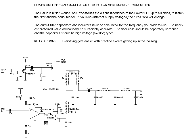
"The PA is pretty bomb-proof. We've had these things running at over 70 Watts! A good output to go for, is to use a mains transformer with a 24 Volt secondary -- recitified and smoothed. The supply needs to be capable of about 3 Amps, and we reckon on about 3000 uF per Amp for the smoothing, so a 10 000 uF capacitor at 40 Volts is ideal. The rig is then capable of about 15 Watts, and can easily be fully modulated with the simple series modulator described. The 22 k preset is adjusted for half rail on the R.F.C. with no audio drive. Some folks have experienced some sort of assymetrical mod, with larger excursions one way than the other, but careful adjustment of this preset will eliminate this problem. (The trapeziod test gives VERY good shapes!)

"The 2N3055 and the 2SK135 should both be heatsunk -- the FET has a source to case connection, so can be bolted straight down, but the 2N3055 must be insulated with the usual mica washer, and plastic bolts or whatever. The heatsink will get hot, especially around the modulator transistor.
"The output filter should be screened (shielded) from the rest of the rig, with each coil screened apart too. It's also a good idea to keep the synthesiser in its own box to keep the digits out of the rest of the rig.
"Hope this inspires some construction!"
Thanks for sharing the circuit, guys!
update: note this newsgroup message from 2002...
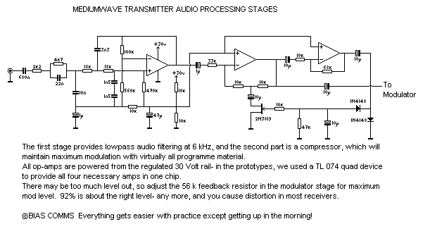
> What's confused me is that you say the Balun is bifilar wound, but you've > got 9 turns on one winding and 17 turns on the other. I can't visualise > exactly how you've wound it, but I'd like to try the circuit out of > curiosity. Does the bifilar winding only extend for 9 turns? Can you > explain it to me please??? Sorry - not too clear - it's actually two windings, with one wound over the other..... > I breadboarded your filter/compressor circuit and I like it. Good! The original was developed over several sessions of "trial and terror" until it was right. > You also > mention that you've had the PA running at over 70 watts, did you get this > much welly by just wanging up the supply voltage to the Darlington pair > and changing the output transformer to go with the changed output impedance? > If so what voltage were you using? We actually paired up the FETs (2SK413s in that instance) and ran the thing at about 95 Volts. We managed to generate some spectacular fireworks when the output filter exploded after the aerial blew down! |