![[MWA Engineering Dept.]](circuitheader.gif)
The "Pixie2" is a simple QRP CW transmitter that dozens of ham radio operators have successfully built. (QRP is ham jargon for low-power operations, and CW is the simplest method of sending Morse code merely by turning a carrier-wave on and off.) The Pixie2 is usually built for the 40 meter band but it will work on frequencies from 1000 kHz up to at least 15 MHz. It is said to output a couple hundred milliwatts of RF.
The circuit can be amplitude modulated quite easily. A small audio amplifier feeds audio current into the 8-ohm side of a transformer. The 1 kilohm side of the transformer is inserted in the V+ supply going to the Pixie's output transistor.
This modified Pixie2 is called the Talking Pixie. It has 18 components (not counting circuit board, jacks, power supply and external audio amp). Building it on a prototyping board only takes a few minutes if all the parts are available.
The level of the audio fed to the transformer is adjusted until the best sound quality is achieved. The Talking Pixie will not sound as loud as commercial stations but the user must avoid the temptation to over-modulate; nobody will listen to an over-modulated signal.
Parts list:
C1: 100 pF
C2: 220 pF
C3: 82 pF
C4: .01
C5: .01
L1: 150 uH
L2: 22 uH
Q1: 2N2222 or 2N3904
Q2: 2N2222A (metal can type) or 2N3866
R1: 47K
R2: 1200
R3: 33K
R4: 10 or 15 ohms (experiment!)
T1: 1000 ohm to 8 ohm audio transformer
The frequency is crystal-controlled. A crystal for the frequency you're interested in will have to be ordered if you don't have one handy.
The transformer must be rated to handle at least half a watt of audio; a very tiny transformer will not sound good and will have too much resistance on the 1K winding.
L3, C6 and C7 form a low-pass filter to attenuate the harmonics generated by the circuit. Specific values for various frequencies can be found on our filters page.
L1 and L2 are factory-made axial molded chokes.
The impedance and bandwidth of the antenna will affect the sound quality of AM transmitters like the Talking Pixie. What sounds good on the test bench with a 50-ohm dummy load attached to the output might not sound as good with real-world antennas like short end-fed wires. Some kind of antenna tuner might be helpful. (By the way, two 100-ohm resistors in parallel make an adequate dummy load for this rig.) Needless to say the size and efficiency of the antenna will have a major impact on the range.
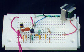
If you build the circuit on a prototyping board (as shown above), also known as a solderless breadboard, you can experiment with many variations on the circuit design.
Because this design cannot achieve a high modulation level, it does not sound loud enough on the air compared to other stations. If you crank up the level of the modulation source you will get a lot of distortion. So, although this circuit is easy to build, it has limited usefulness. I recommend it for newbies who want to gain some confidence in circuit construction before trying to build something more complicated.
Other QRP CW transmitters can also be modified for amplitude modulation. You will find schematics for such transmitters in ham radio books and magazines, and on websites operated by QRP clubs.
This page is explicitly placed in the public domain.
It may be freely reproduced by anyone for any purpose.
Its contents may not be
copyrighted by anyone under any circumstances.