notes on the Gizmo low power AM transmitter
What do you get when you marry a classic PLL oscillator circuit to a slightly modified version of the Wenzel transmitter circuit, and build it on a compact and well-laid-out circuit board the size of a baseball card? You get the Gizmo, an affordable, pocket-size AM transmitter.
As I write these notes in early 2003, the Gizmo is the only assembled, PLL-controlled transmitter available for under $90. It has good audio quality and its range with the supplied wire antenna is sufficient to put a strong signal throughout your house, and possibly your immediate neighbor's house, with weaker reception extending out a block or two. If you add the optional outdoor antenna and the audio processor you can probably boost your range quite a bit; we have not tested all the accessories.
Click here to read the SCWIS review of the Gizmo, with color photographs.
The Gizmo does have room for improvement in a few areas. First off, it is extremely vulnerable to having a buzz or whine in the signal unless you power it from a super highly filtered, ultra-perfect power supply. With the specimen Gizmo that I borrowed from a friend to write this review, this problem was somewhat relieved when I put my finger on the middle chip in the oscillator section, which suggests that a little extra bypass capacitance somewhere in that neighborhood might help.
I'd like to thank Mr. Phil Bolyn for proofreading the diagrams below, and for offering the following comments about the design of the Gizmo:
The RF output consists of a differential amplifier (Q3 and Q4). When Q3 is on, Q4 is off, and vice versa. The transistors are driven to saturation during their respective half cycles. The differential pair method produces highly linear modulation and can be driven to 100% modulation (not true for other, simpler schemes).
Q5 modulates the RF by varying the current to the diff pair at audio rate. The resulting current at Q4 collector is a square wave at RF frequency, amplitude modulated by audio from Q5. The output tank circuit filters out the harmonics. C14 and C15 help to reduce ringing at the current peaks in Q2 and Q4. This should improve the output signal, but I am not convinced they are needed based on spice simulations I have done on a similar circuit.
One problem I see with the Gizmo is the method of tuning the output using a fixed inductor and 4 switch-selectable capacitors. The 4-pole dip switch allows selecting 16 different cap values, but the Q of the output tank is high enough to make this a real compromise. To get max output you would need to carefully select a frequency that matches one of the 16 cap values. Since quiet channels are few in populated areas, it would be pure luck if one of the cap values exactly matched a vacant channel frequency. I would suggest an improvement to the circuit. Mouser Electronics sells an inexpensive 100pf variable trimmer cap. I would add one in parallel to the dip switch to fine tune after selecting the nearest value with the switches.
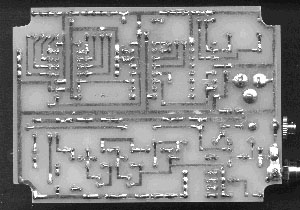
You can't help admiring the Gizmo's elegance and compactness, and it has helped dozens of people to "get their feet wet" in the LPAM waters without having to build something from scratch or purchase a much more expensive assembled transmitter. For those who enjoy looking at circuit designs, here's a peek at the Gizmo's layout. First, the underside of the circuit board: