![[MWA Engineering Dept.]](circuitheader.gif)
![[MWA Engineering Dept.]](circuitheader.gif)

|
Parts list:
|
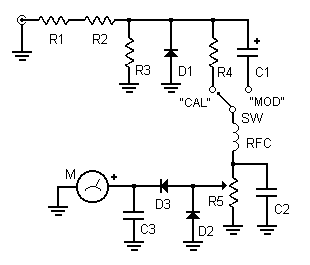
Here is a modulation checker for AM transmitters with up to 5 watts of output power. Keeping modulation levels close to 100% improves range and audibility of a signal, but monitoring the modulation level without an oscilloscope or genuine modulation monitor can be difficult. The circuit shown here might suffice until you can buy an oscilloscope. It is not meant for continuous use; instead, it is temporarily connected to the transmitter's output for occasional check-ups.
Operation: Connect a coaxial jumper from the transmitter's output to the monitor's input. Turn on the transmitter with no audio input (no modulation). Set the function switch to "CAL." Adjust R5 until you get a full-scale (50) reading on the meter. If there's not enough power to produce a 50 reading, use a jumper to bypass R1 and adjust R5 again.
Next, set the function switch to "MOD" and send some audio to your transmitter. When the needle reaches up to about 35 on the meter, this indicates approximately 100% modulation.
A much more sophisticated mod monitor is on the web at this link. A web search on the phrase modulation monitor schematic might turn up some more circuit designs.