The Basics of Bite
How Rear Suspensions Work for Increased Traction
By Jeff Smith - Car Craft Magazine
Horsepower and torque numbers are great for impressing your car buddies. Even
rear-wheel dynos are fun, because big numbers at the rear wheels will inspire
even the most jaded enthusiast. But the final arbiter isn't flywheel torque,
rear-wheel horsepower, or even the number of solenoids under your hood. The
ultimate deal is how well your car can apply all this power to the ground. If
you want to create shock and awe, hook all that torque through the two small
patches where the rear tires meet the road, and the dragstrip groupies will
beat a path to your garage door.
Different Styles
When it comes to rear suspensions, there are many different ways to make it
happen. We'll deal with solid, live-rear-axle applications going in a
straight line for this story and leave the corner-turning tricks for another
time. We'll specifically look at leaf springs, four-links, and torque-arms,
which are the most popular systems for high-performance street machines.
Leaf Springs
Leaf springs are the simplest form of rear suspension since they both locate
the rear axle and suspend vehicle weight. The idea dates back to a time just
after the invention of the wheel. Leaf springs are both heavy and also prone
to wrap-up under high torque loads, which wasn't a problem for our ancestors
in Conestoga wagons. Spring wrap-up occurs when the leading end of the leaf
spring bends sufficiently to bind the rear suspension, at which point it
bounces the tire and wheel off the ground, causing wheelhop. This is an
extremely violent torque reaction that can be easily cured with traction
bars that stiffen the front spring section. Unfortunately, slapper traction
bars also contribute to rear-suspension bind. The most popular leaf-spring
traction devices are CalTracs or Competition Engineering's Slide-A-Link bars,
which act as a lower control arm to prevent spring wrap-up while eliminating
the bind.
Factory Four-Link
This design exchanges heavy leaf springs for much lighter and more compact
coil springs. However, this requires control or trailing arms to connect the
rear axle to the frame. Factory four-links use a pair of lower control arms
matched with a pair of uppers that are angled outward. This angling of the
upper arms locates the rear axle laterally to eliminate the need for a
Panhard bar. This is the rear suspension used in all GM A-bodies like the
Chevelle and also the Fox and SN-95 Mustangs. This rear suspension operates
roughly similar to a drag race four-link, where the upper and lower control
arms are parallel to the framerails. We'll get into more depth with the drag
race four-link shortly.
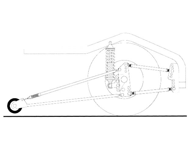
Torque Arm
The torque-arm suspension is the latest factory version of rear suspension
evolution. The torque arm replaces the two upper control arms and is used to
accommodate the application of power through the rear axle and to locate the
rear axle. This requires the help of a Panhard bar to locate the rear axle
laterally. One advantage to eliminating the two upper control arms is
gaining valuable space between the rear axle and the body.
Four link
We'll use this four-link illustration to show how power is applied through the
bars. As torque is applied to the rear axle, the upper bars go into tension,
while the lower bars experience compression. This is why leaf springs bend,
because massive power is applied attempting to compress the spring lengthwise.
Ladder Bar
A ladder-bar system is a simpler version of a four-link with the instant
center located at the fixed pivot point of the bar. You can raise or lower the
IC, but you cannot change its fixed length.
Copyright © Competition Engineering
factory style four-link
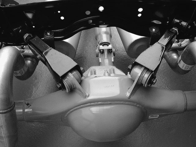
This is a factory-style four-link rear suspension for a '66 Chevelle with a
Currie 9-inch and Hotchkis adjustable upper control arms. The Fox Mustang and
SN-95 platforms employ a similar trailing-arm arrangement. Note how the upper
control arms angle outboard. This triangulation locates the rear axle side to
side, eliminating the need for a Panhard bar.
Pinion angle
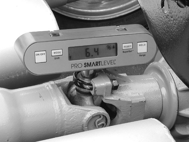
Pinion angle is important to rear suspension efficiency, but don't expect to
see huge gains in e.t. based on a 1- or 2-degree change. The idea is to
minimize driveline angle under acceleration to reduce power loss through the
U-joints. A chassis dyno may be of assistance here in optimizing pinion angle.
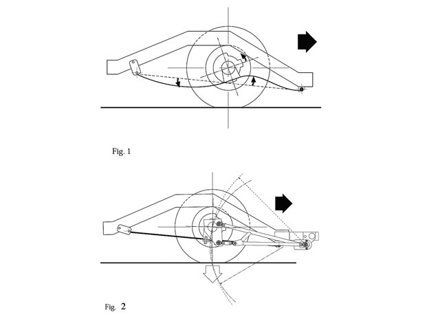
The Application of Power
When power is applied to the pinion gear and into the ring gear of the rear
axle, the pinion tries to climb the ring gear. When viewed from the front of
the car, the clockwise twist of the pinion attempts to lift the right (passenger-side)
rear tire off the ground and plant the left (driver-side) tire. This is the
natural reaction of all rear axles to torque input. This also explains why
drag racers place a certain amount of preload on the right rear tire to
counteract this force. An example of this is the use of an airbag over the
right rear axle that preloads the chassis to counteract this torque reaction.
At the same time that the axle is attempting to lift the right rear tire, the
body is twisting in the opposite direction, which normally results in the body
squatting over the right rear. All of this is the reaction to torque input.
The more torque you apply or the more gear ratio you use to multiply the
torque, the more twisting effort is applied to the chassis. Drag racers and
suspension engineers have collaborated to create very specific ways to explain
how all this happens and have also come up with ways to manage the power in a
systematic fashion.
Instant Center
All vehicles have a specific point around which the entire car will balance
called the center of gravity (CG). For most domestic front-engine, rear-drive
cars, the CG is generally located forward of the mid-point of the car at
around camshaft height off the ground. While all rear suspensions pivot around
a given point, this is not necessarily the point at which the rear suspension
applies power or lift. Suspension engineers call this lift point the instant
center (IC). Different suspensions place this IC at different positions in the
car. Because suspension components tend to shift as the body lifts or squats,
this position is dynamic, meaning that it moves as the car pitches or rolls.
One definition of IC is the unseen center of an arc created by the moving
suspension links. The simplest instant center is a drag race ladder bar. The
forward mounting point for the ladder bar where it hooks to the chassis also
happens to be its instant center. With other rear-suspension designs, the
instant center is an imaginary point in space.
Kevin Gertgen's Performance Trends has created a drag race four-link computer
simulation program called 4 Link that offers pictures that tell the story much
easier. If you look at the illustration, you'll notice a pair of dotted lines
that extend from the lines drawn by the two upper control arms and the two
lower control arms. The intersection point of those two lines is called the
instant center. The 4 Link program allows you to reposition the IC by moving
the mounting points of the upper and lower control arms. Also notice the
dotted line that extends from the rear-tire contact point forward at an angle.
This line intersects a point created by the intersection of the horizontal CG
line with a vertical line drawn through the front spindle. This angled line is
called the 100 percent antisquat line, or sometimes called the neutral line.
By changing the location of the upper and lower four-link bars, you can move
the IC location either above, directly on, or below that 100 percent antisquat
line. When the IC is positioned below that 100 percent antisquat line, the
rear of the car will squat on acceleration and "hit" the tires
relatively softly. When the IC is positioned above the 100 percent antisquat
line, the rear of the car will tend to rise on acceleration and
"hit" the tires harder. Obviously, if the IC is placed directly on
the 100 percent line, the rear will remain neutral.
This explanation holds true for all rear-drive cars, but there is plenty of
confusion around the location of the instant center with different suspension
systems. For example, with leaf-spring cars, the IC is the front spring eyes,
but with ladder bars, the IC is the front pivot point. Factory four-link cars
are determined exactly the same way as drag race four-link systems. If you
extend imaginary lines forward on a factory four-link rear suspension, the IC
generally falls in front of the car, well below the 100 percent antisquat line.
This is why all factory four-link cars squat on acceleration. By installing
the Lakewood anti-hop bars (for example), this kit raises the rear locating
point of the upper control arms roughly 2 inches. This shortens the IC length
and also places it above the 100 percent antisquat line, which now helps plant
the rear tires.
Conclusion
So, what have we learned here? The main thing to take away from this rear
suspension discussion is that there's more to improving traction than just
dumping 50 pounds of ballast in the trunk. You can use specific suspension
components to help you create optimal traction, but only if you understand how
all these components work. This has been a primer intended to introduce you to
the ideas around rear suspension science. There are dozens of other variables
like weight distribution, engine torque, shock tuning, tire pressures, and of
dozens more that contribute to improving traction. That's why this is as much
art as it is science. But when you get it to work for you, your car will make
you out to be a low-e.t. hero.