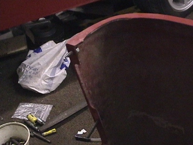
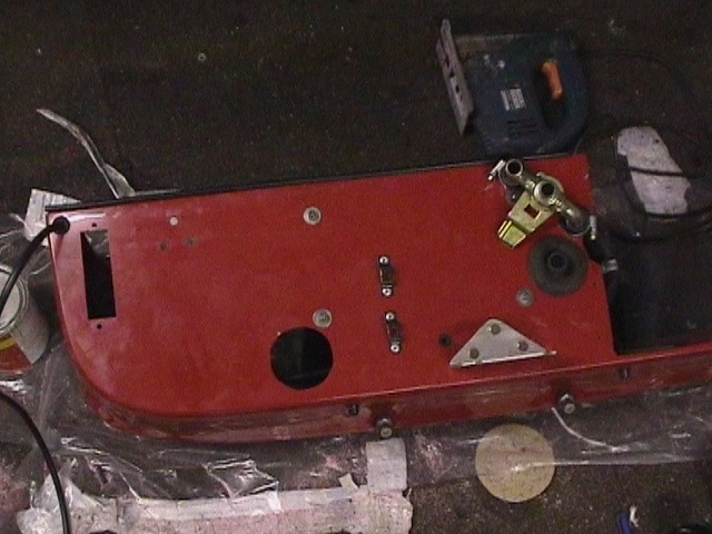
 a
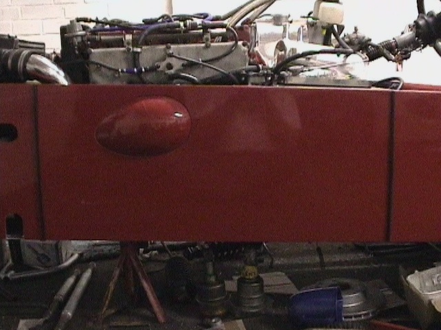
second cut 2 inches back from the front suspension outlets gave a removable
engine side panel section. It goes without saying how much easier things like
oil filter changing are
a
second cut 2 inches back from the front suspension outlets gave a removable
engine side panel section. It goes without saying how much easier things like
oil filter changing areQuadraRushABS (2)
a
second cut 2 inches back from the front suspension outlets gave a removable
engine side panel section. It goes without saying how much easier things like
oil filter changing are
 self
tappers were used for the lateral positioning of the side panels
self
tappers were used for the lateral positioning of the side panels
 a
61 inch length is shaped to fit scuttle
a
61 inch length is shaped to fit scuttle
 winged
piping was curved around and fixed with a c'sunk self tapping screw
winged
piping was curved around and fixed with a c'sunk self tapping screw
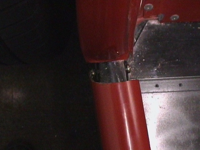
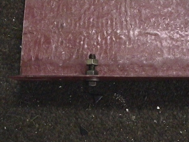 after
tapping the lower chassis rail a 6mm bolt, washer and 2 nuts gave the ability to
position the base of the side panel
after
tapping the lower chassis rail a 6mm bolt, washer and 2 nuts gave the ability to
position the base of the side panel
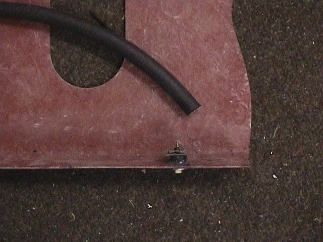 self
tappers used to attach lower edge of side panel to infill panels with fuel hose
used a spacer tube
self
tappers used to attach lower edge of side panel to infill panels with fuel hose
used a spacer tube
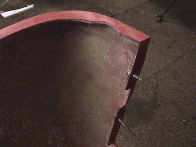 self
tappers and through bolts used to attach nose cone
self
tappers and through bolts used to attach nose cone
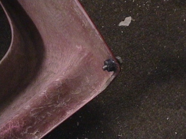 lower
corners of nose cone attached to chassis with M6 bolts tapped directly into
chassis
lower
corners of nose cone attached to chassis with M6 bolts tapped directly into
chassis
 just
one self tapper used on LHS of nose cone
just
one self tapper used on LHS of nose cone
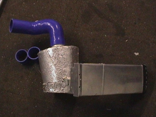
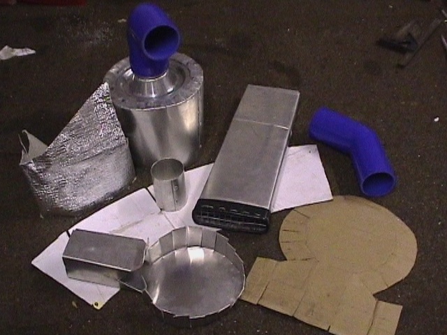 component
parts of air intake assembly
component
parts of air intake assembly
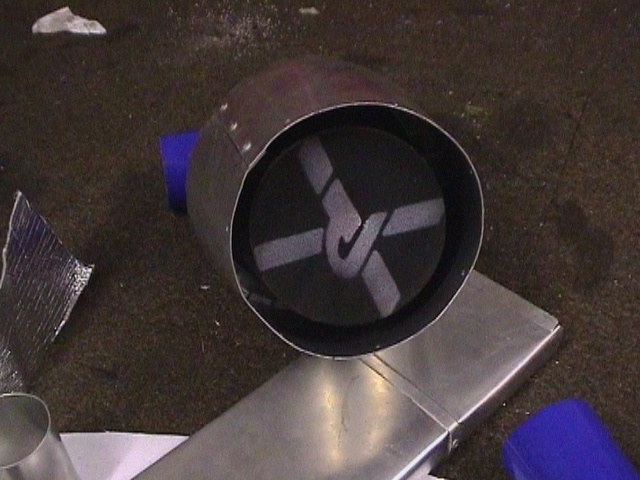 air
filter casing attached to an RS500 cone filter
air
filter casing attached to an RS500 cone filter
 the
rear gearbox cradle and mounting bolts were ground down to give a clearance to
the chassis rail
the
rear gearbox cradle and mounting bolts were ground down to give a clearance to
the chassis rail
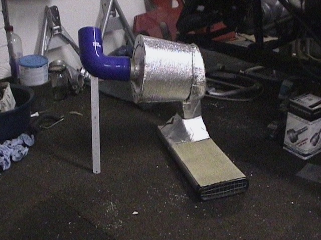 air
intake assembly. Cross sectional area maintained is greater than the 3 inch
diameter connecting pipes
air
intake assembly. Cross sectional area maintained is greater than the 3 inch
diameter connecting pipes
 two
6mm holes at the back of the air intake for water drainage
two
6mm holes at the back of the air intake for water drainage
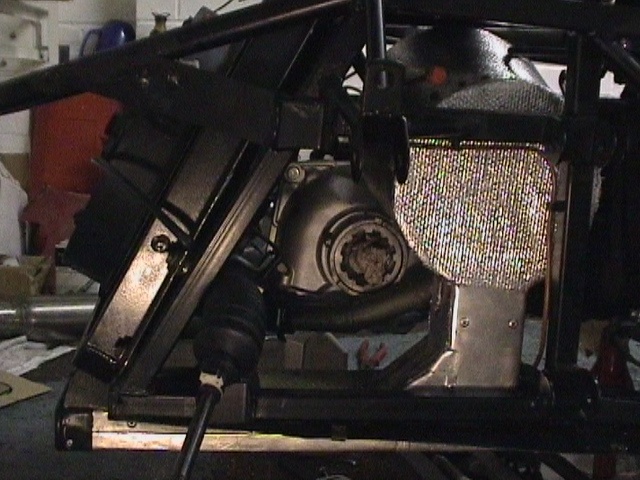 air
intake assembly in LHS front of chassis
air
intake assembly in LHS front of chassis
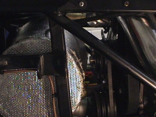 air
casing has a 10mm clearance to the water pump pulley
air
casing has a 10mm clearance to the water pump pulley
 cropped
90° and 45° 3 inch elbows connect air casing to compressor
cropped
90° and 45° 3 inch elbows connect air casing to compressor
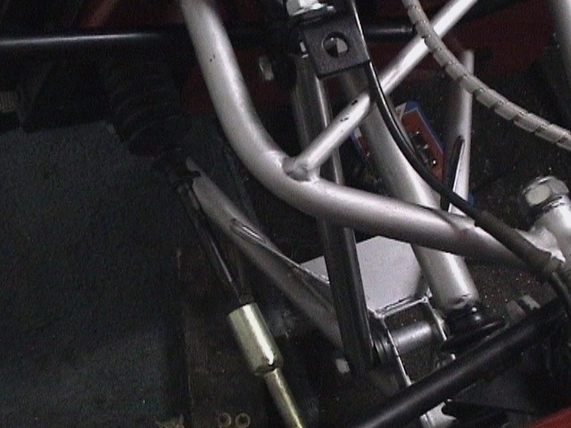
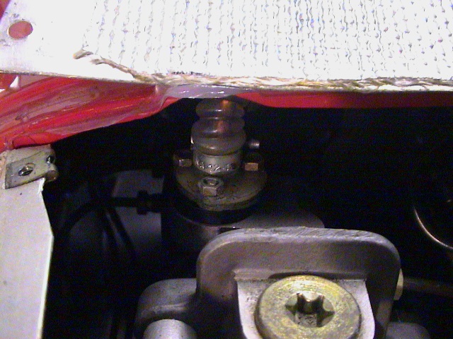
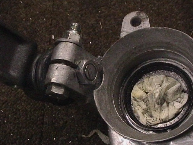 the
lower ball joint was cut down flush with the special nut
the
lower ball joint was cut down flush with the special nut
 assembled
front hub with ABS sensor
assembled
front hub with ABS sensor
 front
upper wishbone was assembled with the ball joint sloping down towards the car
front
upper wishbone was assembled with the ball joint sloping down towards the car
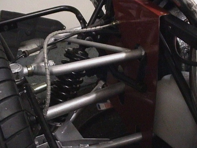
 front
struts 287mm between centres sets the correct ride height before 4 wheel
alignment
front
struts 287mm between centres sets the correct ride height before 4 wheel
alignment
 rear
struts were 320mm between centres
rear
struts were 320mm between centres
 2.5mm
ground off one side of wheel box spacer tube allowed its correct alignment
2.5mm
ground off one side of wheel box spacer tube allowed its correct alignment
 the
windscreen pillar was fitted with its lower edge parallel to the base of the
scuttle
the
windscreen pillar was fitted with its lower edge parallel to the base of the
scuttle
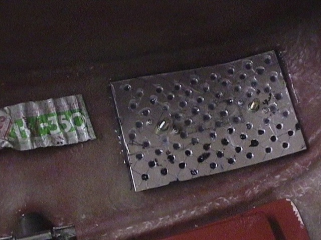 2
holes were enlarged to 12mm diameter for the captive bolts which were then
riveted in position. The plate was glued down mostly with HV350 with Wurth
acting as a gap filler
2
holes were enlarged to 12mm diameter for the captive bolts which were then
riveted in position. The plate was glued down mostly with HV350 with Wurth
acting as a gap filler
 6mm
was removed from the demisting duct at its rear edge to give clearance to the
wheel boxes
6mm
was removed from the demisting duct at its rear edge to give clearance to the
wheel boxes
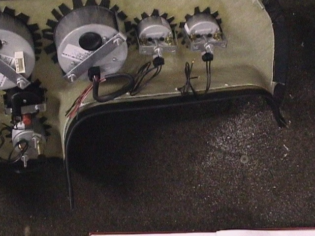
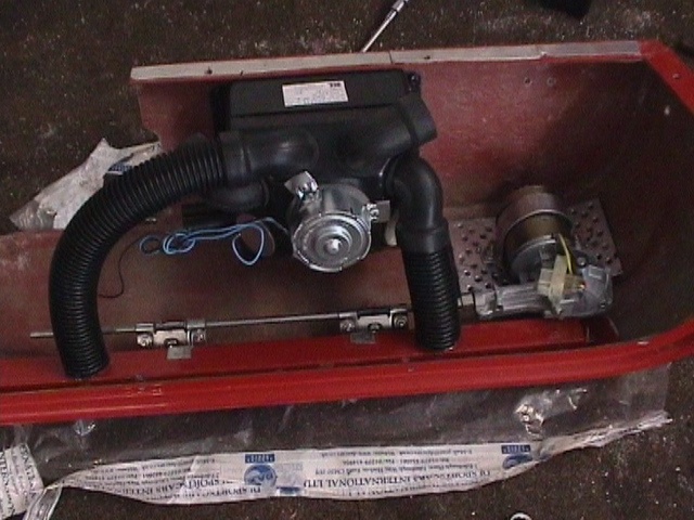 assembled
wiper motor and heater unit
assembled
wiper motor and heater unit
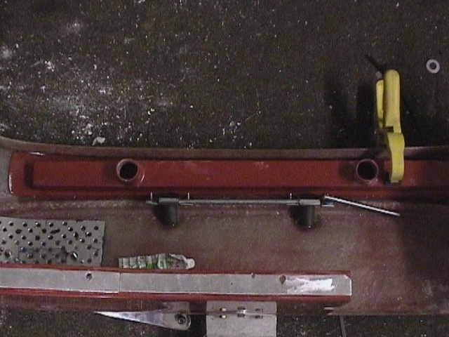
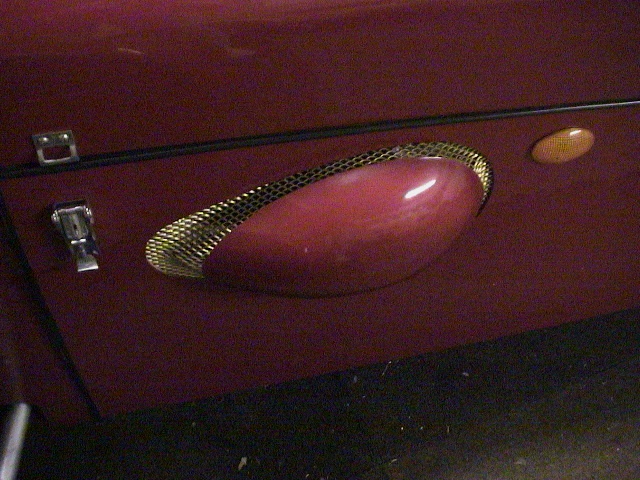
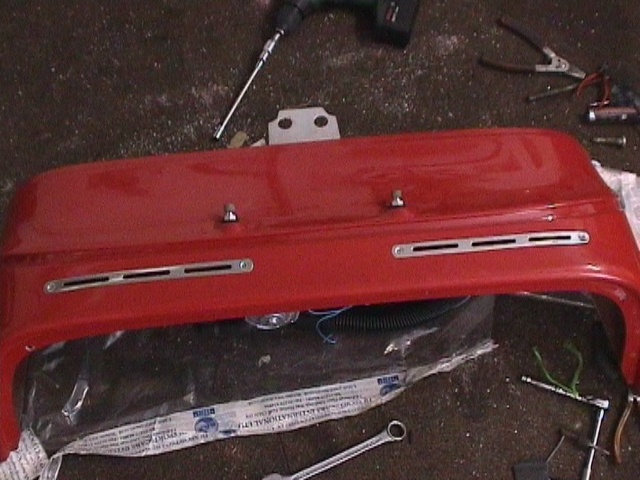 escutcheon
plates are more easily fitted before the de-mister duct
escutcheon
plates are more easily fitted before the de-mister duct
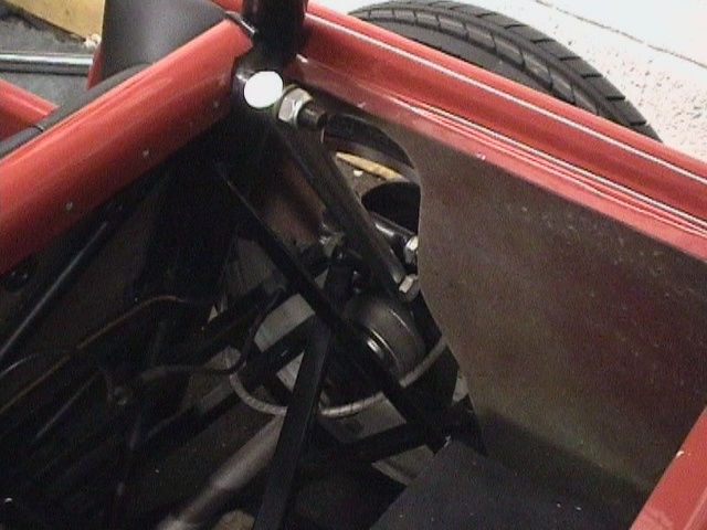
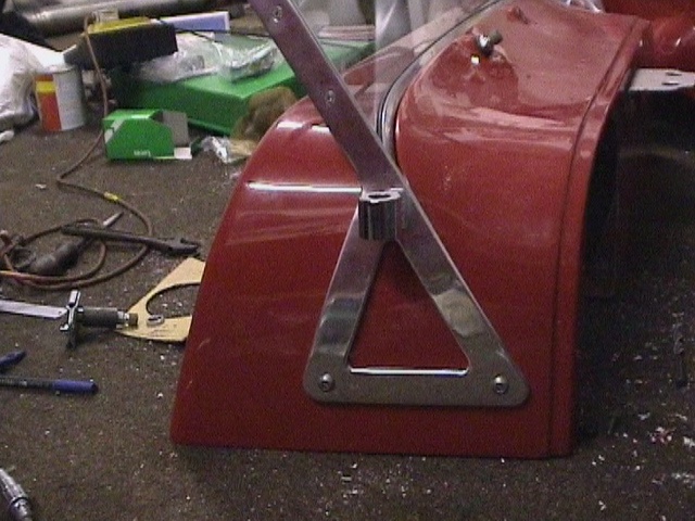
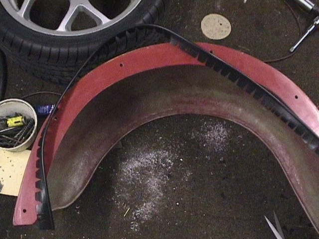
 the
cycle wing bracket ends were rough ground and bent to a different shape to give
a better fit and adhesion to the front mudguards
the
cycle wing bracket ends were rough ground and bent to a different shape to give
a better fit and adhesion to the front mudguards
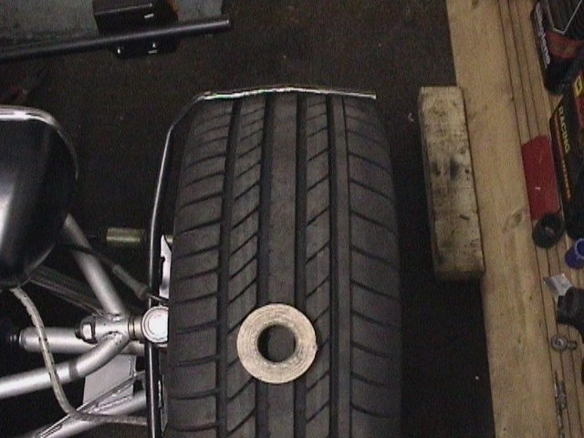
 a
reel of insulation tape was just right to keep the mudguard equi-spaced around
the tyre
a
reel of insulation tape was just right to keep the mudguard equi-spaced around
the tyre
 two
5 inch square fibreglass patches gave a mechanical lock for the mudguards
two
5 inch square fibreglass patches gave a mechanical lock for the mudguards
 only
2 of the 7 rear mudguard bolts screwed directly into the chassis
only
2 of the 7 rear mudguard bolts screwed directly into the chassis
 the
winged piping was feathered to allow it to curve around the rear mudguards
the
winged piping was feathered to allow it to curve around the rear mudguards
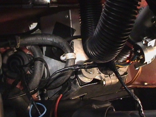
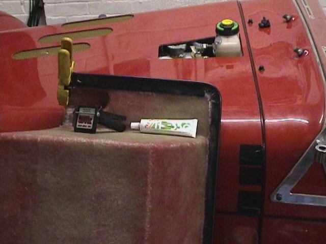
 65
and 55mm holes were needed for grommets carrying the engine and ABS looms. The
'H' configuration heater valve from Dax allows flow to the heater to be turned
on or off without preventing flow to the oil modine.
65
and 55mm holes were needed for grommets carrying the engine and ABS looms. The
'H' configuration heater valve from Dax allows flow to the heater to be turned
on or off without preventing flow to the oil modine.
 shot
inside the scuttle showing the rear pedal box shields. With up to 3000psi brake
fluid pressure, you dont really need any direct leak paths to the cockpit!
shot
inside the scuttle showing the rear pedal box shields. With up to 3000psi brake
fluid pressure, you dont really need any direct leak paths to the cockpit!
 the
end of the engine loom was also re-wrapped to give the throttle position sensor
connection
the
end of the engine loom was also re-wrapped to give the throttle position sensor
connection
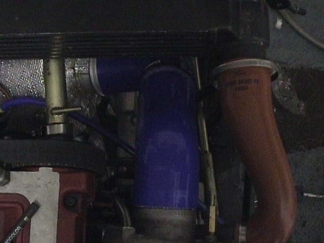
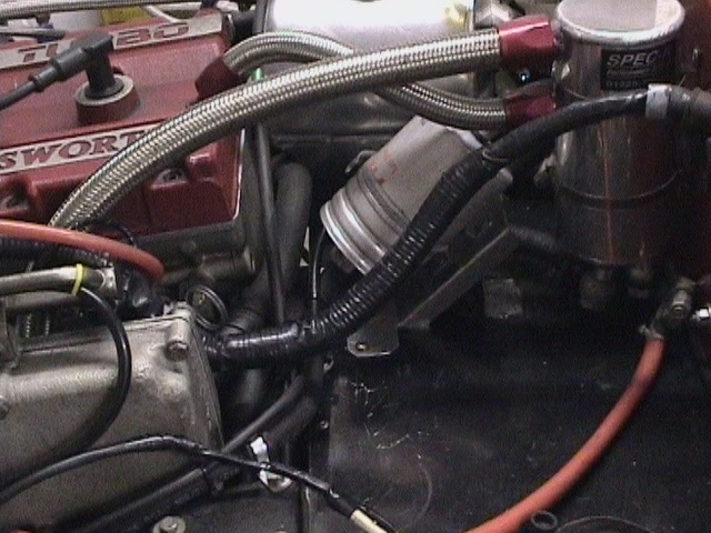
 Escort
Cosworth swirl pot mounted behind intercooler minimises air in the cooling
system
Escort
Cosworth swirl pot mounted behind intercooler minimises air in the cooling
system
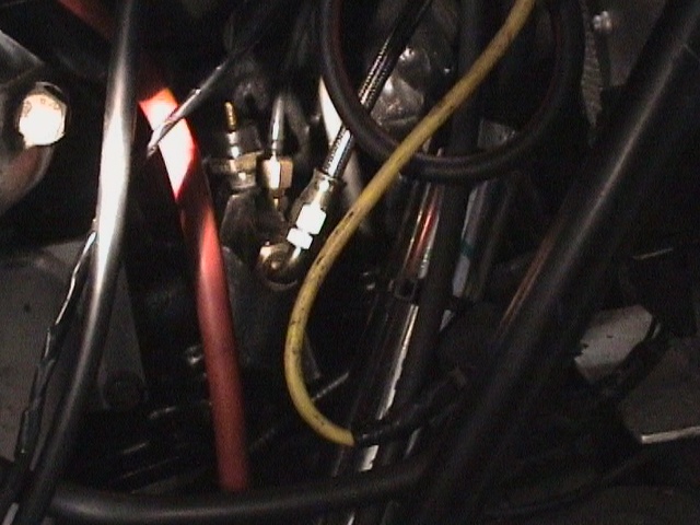
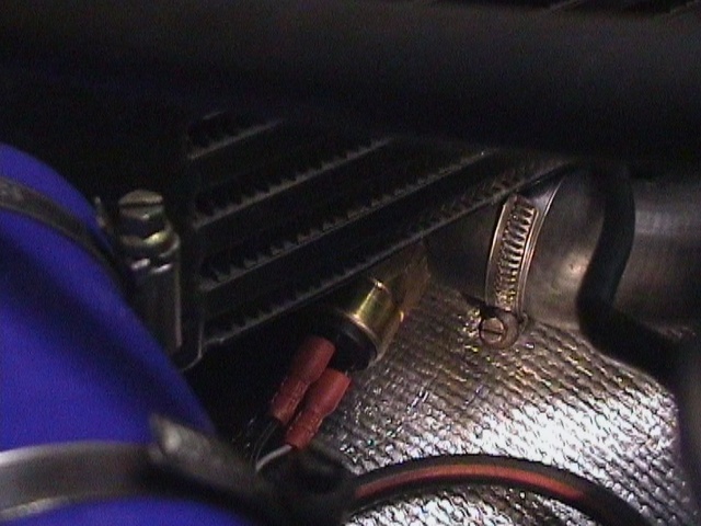 a
low water pressure sensor (0 to 7psi - set just above 0psi) was tapped into the
upper steel pipe
a
low water pressure sensor (0 to 7psi - set just above 0psi) was tapped into the
upper steel pipe
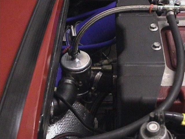
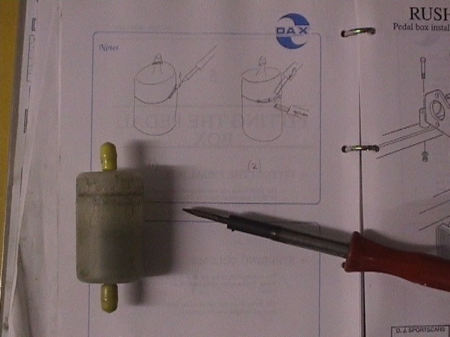
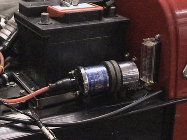
 the
fuel
filter was mounted in last available space!
the
fuel
filter was mounted in last available space!
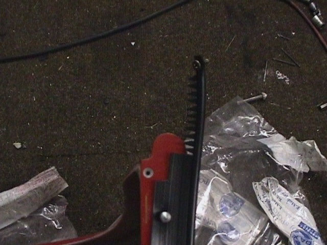
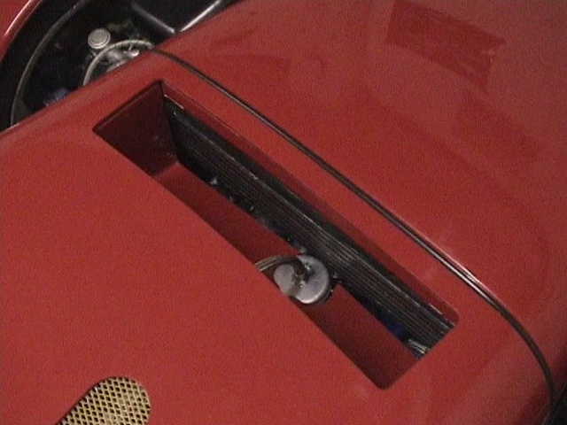
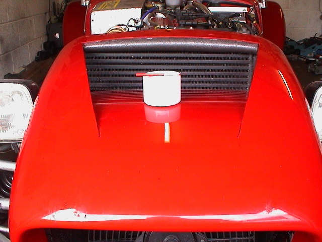
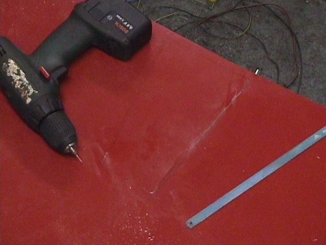 the
aperture in the top of the bonnet was made by chain drilling with a 1mm drill
and cutting with a hacksaw blade
the
aperture in the top of the bonnet was made by chain drilling with a 1mm drill
and cutting with a hacksaw blade
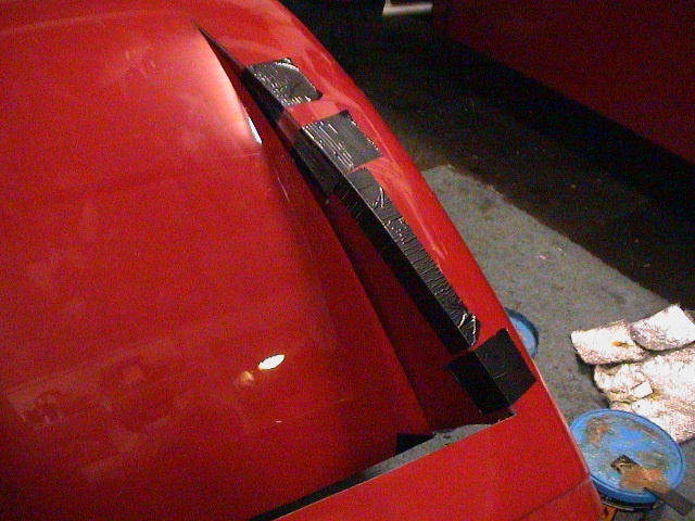
 the
winged piping was glued on the inside of the bonnet and boot using HV350 and
held in position with clamps and duct tape
the
winged piping was glued on the inside of the bonnet and boot using HV350 and
held in position with clamps and duct tape
 the
bonnet rails were reduced in width by 9mm and held in place with 8mm hex headed
self drilling self tappers from Screw-fix
the
bonnet rails were reduced in width by 9mm and held in place with 8mm hex headed
self drilling self tappers from Screw-fix
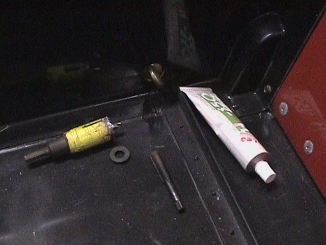
 two
halves of ABS high pressure pump filter housing plastic welded together with a
soldering iron to pass a pressure test of 5psi (only sees pressure due to head
in reservoir)
two
halves of ABS high pressure pump filter housing plastic welded together with a
soldering iron to pass a pressure test of 5psi (only sees pressure due to head
in reservoir)
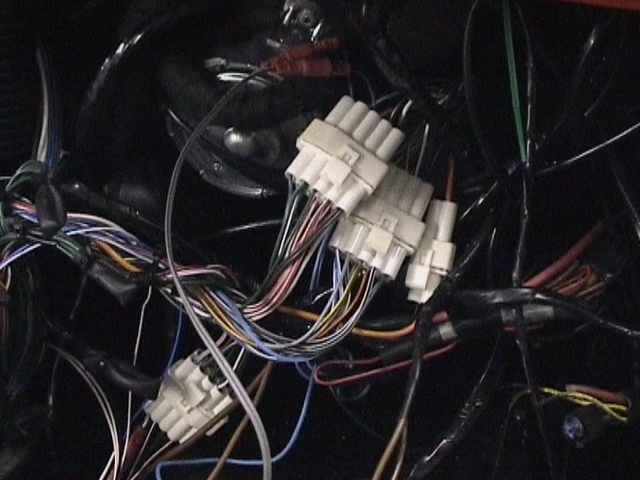 on
the Dax loom there are 3 connectors to the front harness and 1 to the rear
on
the Dax loom there are 3 connectors to the front harness and 1 to the rear
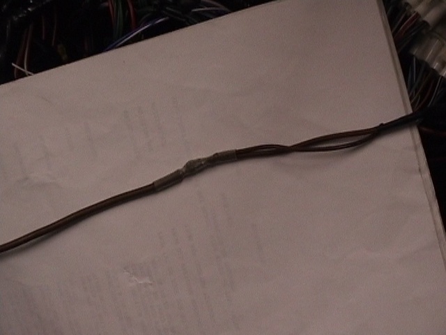 the
twin lead brown earth from the ABS loom was extended to reach the ABS valve
block unit
the
twin lead brown earth from the ABS loom was extended to reach the ABS valve
block unit
 Dax
adaptor for the line off to the hydraulic oil pressure gauge
Dax
adaptor for the line off to the hydraulic oil pressure gauge
 the
rubber mounted ignition coil support was made from a Lancia petrol filter holder
the
rubber mounted ignition coil support was made from a Lancia petrol filter holder
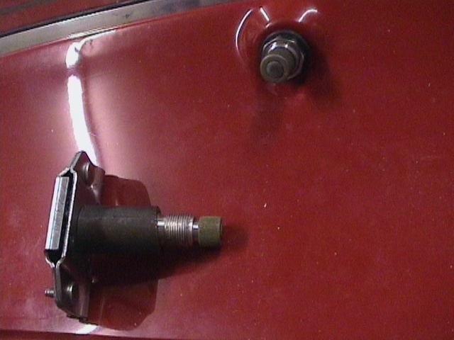
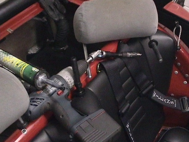
 the
seat belt lower anchorages were accessed using a 27mm box drill and sealed off
with HV350
the
seat belt lower anchorages were accessed using a 27mm box drill and sealed off
with HV350
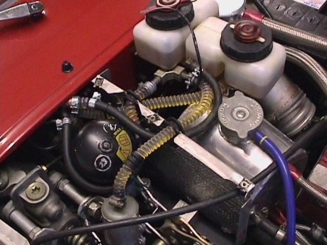
 the
master cylinder front bayonet was originally 2 bayonets cut from the Sierra
reservoir and plastic welded together. This was later replaced with 2 bayonets
bolted together with an HV350 covered gasket due to the extra bending moments
applied by the coaxial tubes attached. HV350 was also applied to all fittings
and allowed to cure to act as a soft seal before clamping on the Teflon hose
the
master cylinder front bayonet was originally 2 bayonets cut from the Sierra
reservoir and plastic welded together. This was later replaced with 2 bayonets
bolted together with an HV350 covered gasket due to the extra bending moments
applied by the coaxial tubes attached. HV350 was also applied to all fittings
and allowed to cure to act as a soft seal before clamping on the Teflon hose
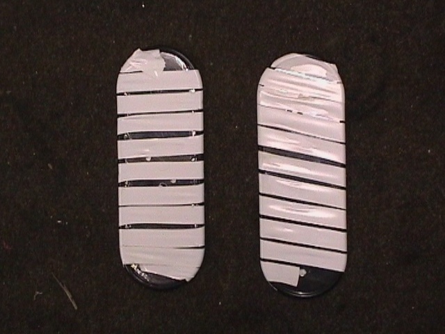 the
rear light cluster plates had strip edging glued using HV350 on one side only
the
rear light cluster plates had strip edging glued using HV350 on one side only
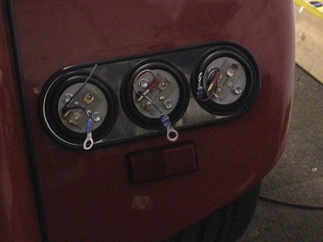 8mm
headed self tappers fixed rear light units
8mm
headed self tappers fixed rear light units
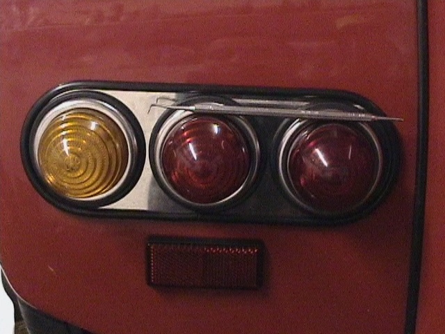 a
dental
probe used to fit lenses and bezels
a
dental
probe used to fit lenses and bezels
 the
Dax front harness came down the RHS of the car with dual connectors either side
for different engine ancillaries
the
Dax front harness came down the RHS of the car with dual connectors either side
for different engine ancillaries
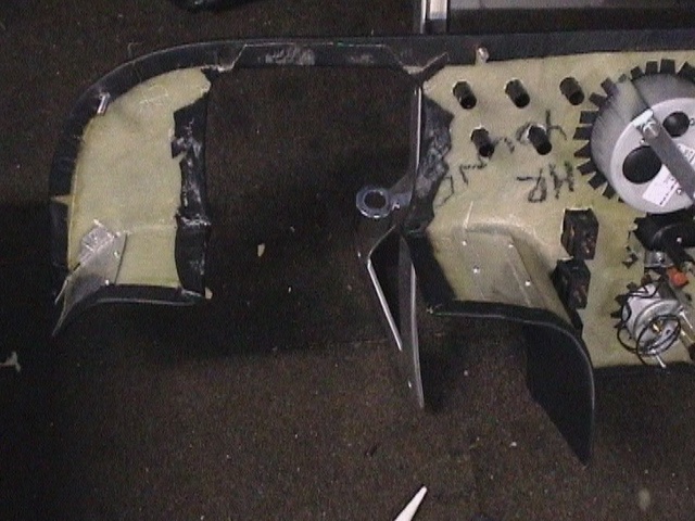 the
RHS of a Dax dash was modified to allow a higher steering column for more leg
room
the
RHS of a Dax dash was modified to allow a higher steering column for more leg
room
 the
passenger side was reduced by 25mm to allow room for the Engine and ABS ECU's
(may as well have made the Dash!)
the
passenger side was reduced by 25mm to allow room for the Engine and ABS ECU's
(may as well have made the Dash!)
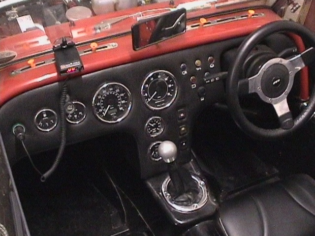
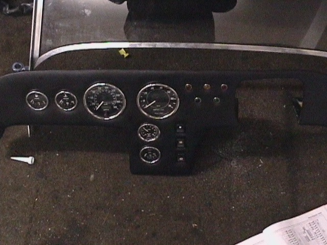 assembled
dash with all but the low water pressure blue warning light
assembled
dash with all but the low water pressure blue warning light
 2nd
oversize Mahle piston
2nd
oversize Mahle piston
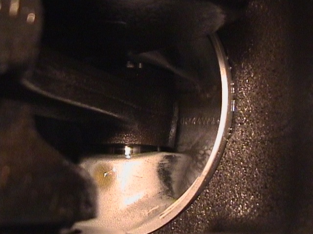
 cause
of initial low engine oil pressure! 6mm bolt, a thin plate and araldite?!! What
the engine builder should not have done when using a block modified for EEC IV
oil jets but using the 2wd piston spray bar. Block now contains capped off EEC
IV oil jets giving a proper seal and achieving a 75psi max oil pressure
cause
of initial low engine oil pressure! 6mm bolt, a thin plate and araldite?!! What
the engine builder should not have done when using a block modified for EEC IV
oil jets but using the 2wd piston spray bar. Block now contains capped off EEC
IV oil jets giving a proper seal and achieving a 75psi max oil pressure
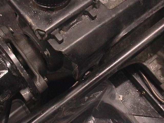
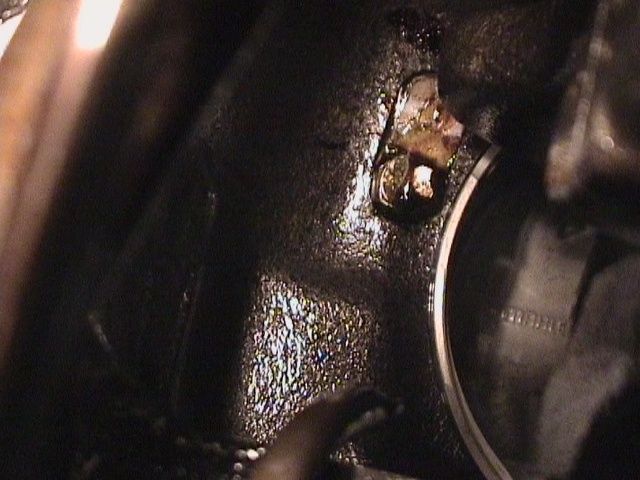
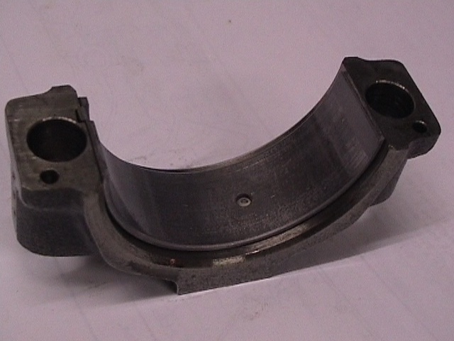 damage
after only 400 miles in the donor vehicle arising by the incredible use of the
original (and just cant imagine!) uncleaned oil pump!!! Engine now has new big
end and main shells and a new high pressure oil pump less.....
damage
after only 400 miles in the donor vehicle arising by the incredible use of the
original (and just cant imagine!) uncleaned oil pump!!! Engine now has new big
end and main shells and a new high pressure oil pump less.....
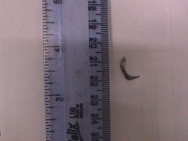 this
unfrazed and left attached waiting to fall off in the oil pump body by Ford!
arghhhhhh!!!!
this
unfrazed and left attached waiting to fall off in the oil pump body by Ford!
arghhhhhh!!!!
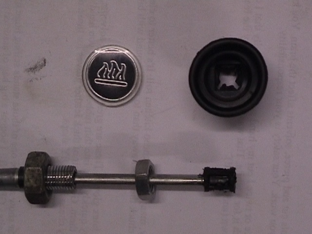 heater
control knob modified to allow it to pass through the dash
heater
control knob modified to allow it to pass through the dash
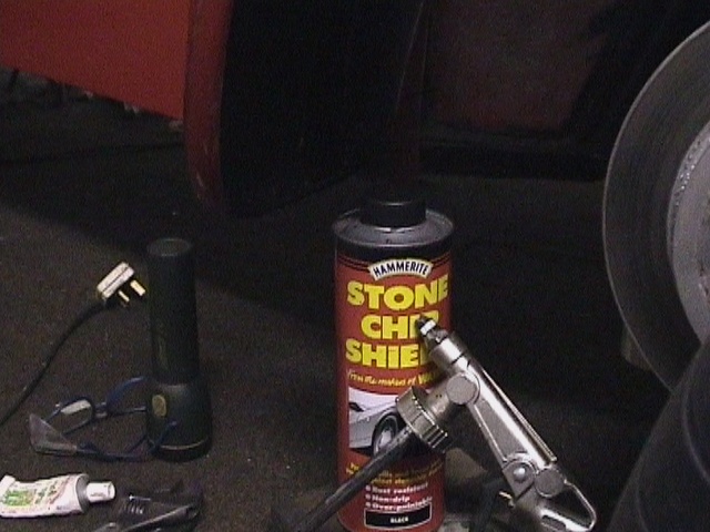 Stoneguard
was spayed on the inside of the 4 mudguards to minimise cracks and dents due to
flying stone - all credit to dax@se7ens list!!
Stoneguard
was spayed on the inside of the 4 mudguards to minimise cracks and dents due to
flying stone - all credit to dax@se7ens list!!
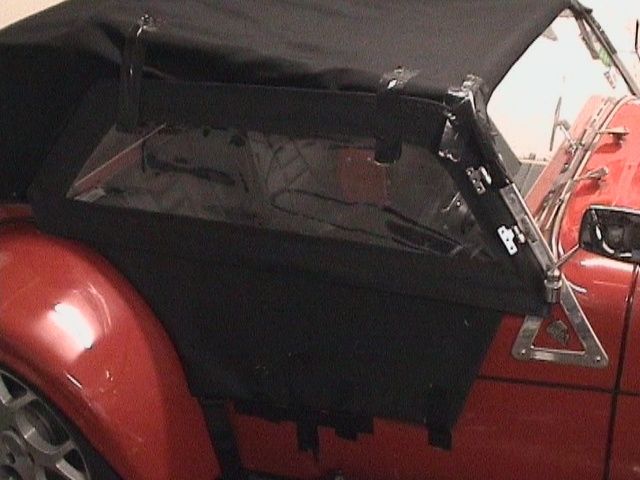
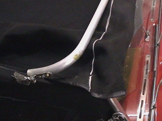
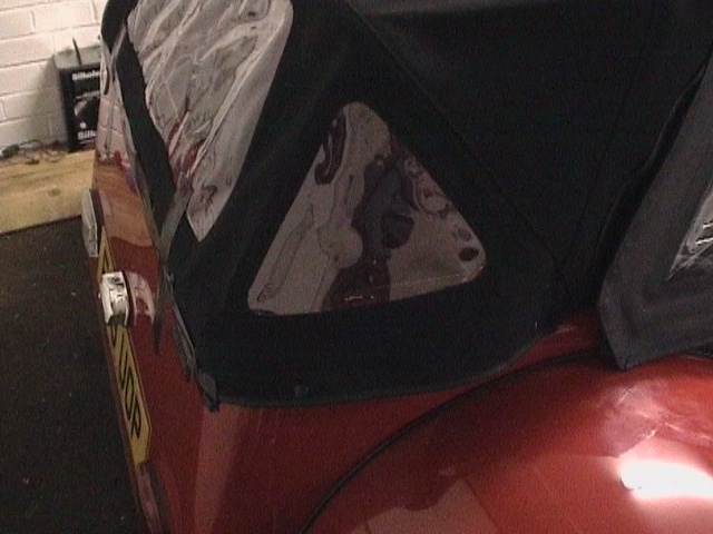 the
Dax hood studs determined the position of the studs on the rear tub for the rear
tonneau
the
Dax hood studs determined the position of the studs on the rear tub for the rear
tonneau
 everything
taped into position to determined best place for doors
everything
taped into position to determined best place for doors
 studs
fitted just below line of curve on rear tub allowed standard rear tonneau to fit
over the hood
studs
fitted just below line of curve on rear tub allowed standard rear tonneau to fit
over the hood
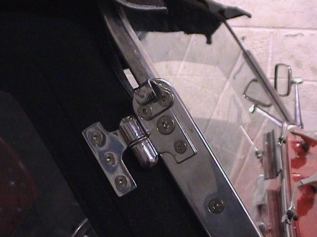 the
top of upper door hinge was removed to allow better locking action of the hood
over centre clip
the
top of upper door hinge was removed to allow better locking action of the hood
over centre clip
 with
the best position achieved a chalk line was used to reposition with impact
adhesive
with
the best position achieved a chalk line was used to reposition with impact
adhesive
 plastic
inserts used to locate Sierra head restraints were easily removed from Sierra
seats by twisting 90° and were bonded into holes in the Rush cross member made
with a 16mm box drill
plastic
inserts used to locate Sierra head restraints were easily removed from Sierra
seats by twisting 90° and were bonded into holes in the Rush cross member made
with a 16mm box drill
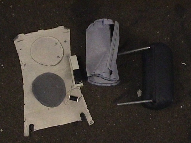 new vinyl head rest covers produced from pattern made from unstitched old covers
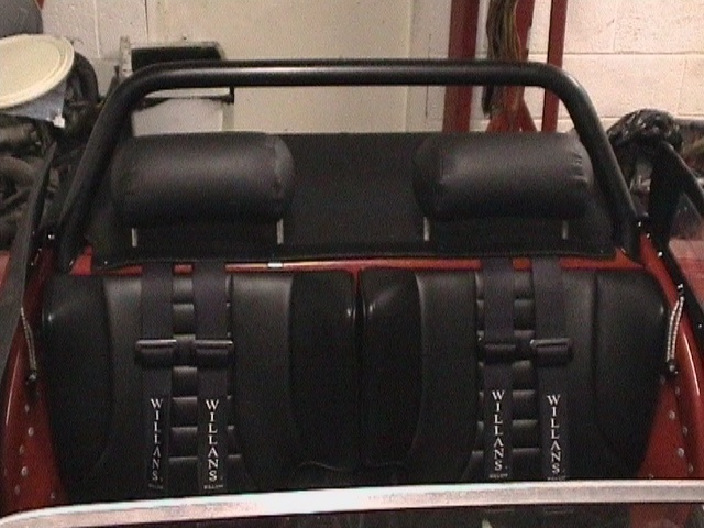 finished
head restraints
finished
head restraints
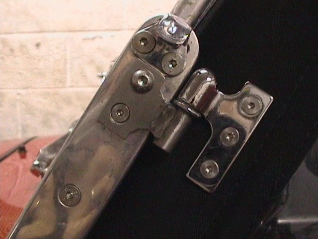 brass
door hinges have a tendency to snap off (dont they John!) Before I learned that
Dax will replace them with stainless one I made these using the redundant
standard stainless brake reservoir bracket
brass
door hinges have a tendency to snap off (dont they John!) Before I learned that
Dax will replace them with stainless one I made these using the redundant
standard stainless brake reservoir bracket
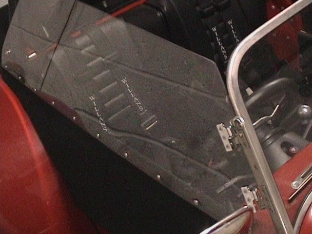 4mm
polycarbonate was used to make less claustrophobic transparent windows
4mm
polycarbonate was used to make less claustrophobic transparent windows
 a
bonnet duct was cut in to allow air to pass out of the bonnet from the
intercooler
a
bonnet duct was cut in to allow air to pass out of the bonnet from the
intercooler
 with
the XR4x4 donor vehicle discs, off the shelf pads and 280 road tyres the ABS
pulled over a 'g' under braking. This was about double what the car achieve with
the ABS turned off
with
the XR4x4 donor vehicle discs, off the shelf pads and 280 road tyres the ABS
pulled over a 'g' under braking. This was about double what the car achieve with
the ABS turned off
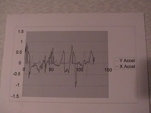
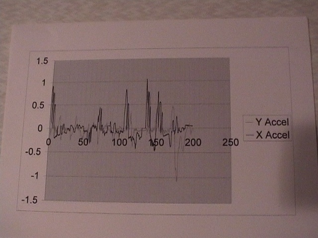 Haven't
yet had it on a rolling road with full boost, but a Dyno Plus Road accelerometer
with 920kg all up weight gave 292bhp. So allowing for wind resistance and 27%
transmission losses the engine gross power cannot be far off 400bhp at 25psi
boost. Even with the 280 Continentals the car was pulling over a 'g' in any
direction.
Haven't
yet had it on a rolling road with full boost, but a Dyno Plus Road accelerometer
with 920kg all up weight gave 292bhp. So allowing for wind resistance and 27%
transmission losses the engine gross power cannot be far off 400bhp at 25psi
boost. Even with the 280 Continentals the car was pulling over a 'g' in any
direction.
 to
hit 25psi boost the actuator needed strapping to the compressor which feeds the
actuator directly
to
hit 25psi boost the actuator needed strapping to the compressor which feeds the
actuator directly
 First
11 laps of the track had the 280 UTQG road tyres struggling for grip, boost
cutting the spark at 26psi and a blown off intercooler hose due to an
insufficient lip on the intercooler to throttle connecting pipe, oh and the
brakes got fried by the ABS! (thanks again for the pic Mike!)
First
11 laps of the track had the 280 UTQG road tyres struggling for grip, boost
cutting the spark at 26psi and a blown off intercooler hose due to an
insufficient lip on the intercooler to throttle connecting pipe, oh and the
brakes got fried by the ABS! (thanks again for the pic Mike!)
 a
'Y' piece with coaxial pipe (attaching to coaxial copper pipe inside the Teflon
pipe) now feeds a 4th line returning boiling brake fluid back to the auxiliary
brake reservoir
a
'Y' piece with coaxial pipe (attaching to coaxial copper pipe inside the Teflon
pipe) now feeds a 4th line returning boiling brake fluid back to the auxiliary
brake reservoir
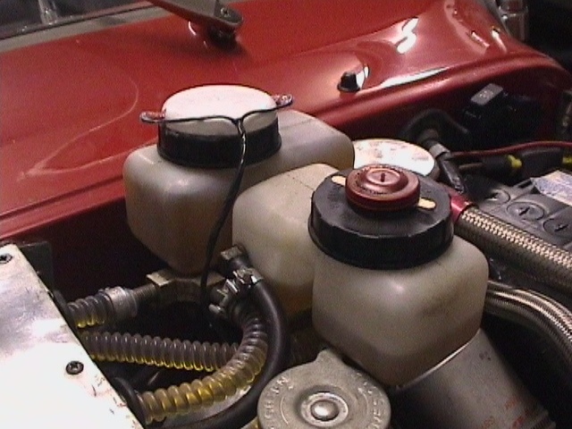 the
rear brake reservoir has now been capped of using HV350 to prevent fluid surge
under heavy braking
the
rear brake reservoir has now been capped of using HV350 to prevent fluid surge
under heavy braking
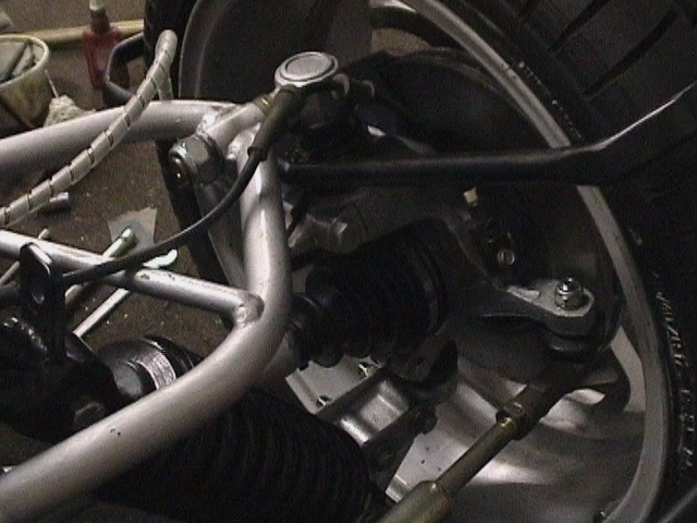
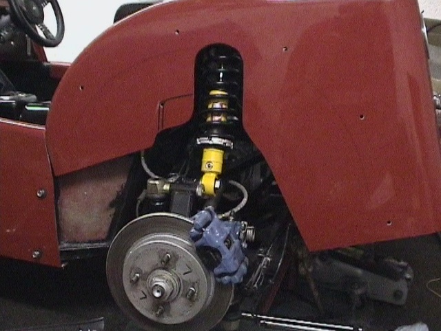
 the
rear ABS sensors were originally set up with 0.5mm hub clearance, but the ABS
would cut out at low speeds with the warning light coming on. The gap has been
reduced by removing a 0.3mm shim from both sides. G-Tec Pro meter is just for
extra passenger entertainment!
the
rear ABS sensors were originally set up with 0.5mm hub clearance, but the ABS
would cut out at low speeds with the warning light coming on. The gap has been
reduced by removing a 0.3mm shim from both sides. G-Tec Pro meter is just for
extra passenger entertainment!
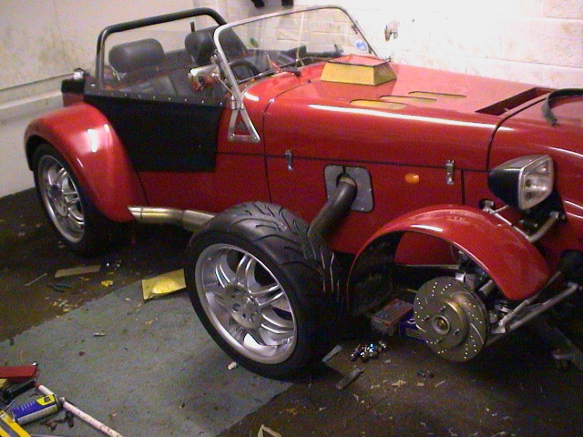 EBC
cast iron discs worked well on the bikes and albeit a LHS disc, this is an EBC
'Trackday' item running with DS2000 Ferodo pads
EBC
cast iron discs worked well on the bikes and albeit a LHS disc, this is an EBC
'Trackday' item running with DS2000 Ferodo pads
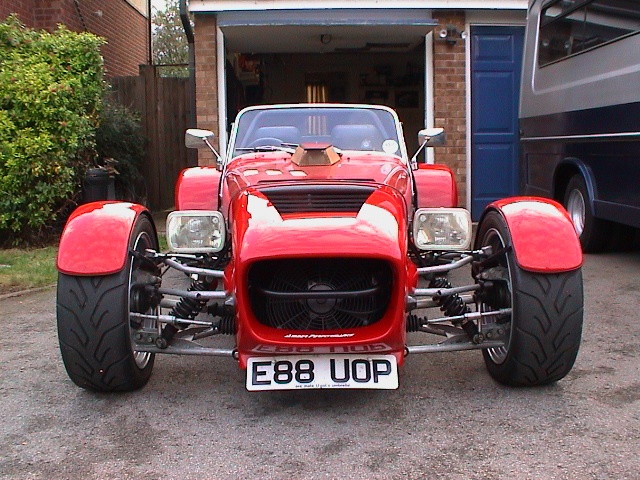
 the
front mudguards have now been refitted to house the 225/45x17 A048 tyres
the
front mudguards have now been refitted to house the 225/45x17 A048 tyres
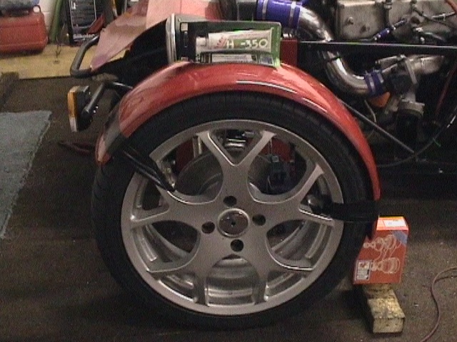
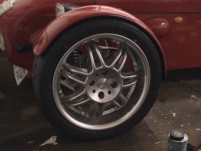
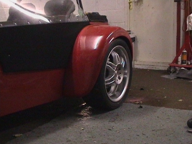 these
Momo 'Racer' wheels and Yokohama tyres now fill the 'narrow' Dax wheel arches
(about 1mm clearance with the shock removed and the wheel pushed right up in the
arch). The front edge of the rear mudguards had to be moved forward to achieve
this
these
Momo 'Racer' wheels and Yokohama tyres now fill the 'narrow' Dax wheel arches
(about 1mm clearance with the shock removed and the wheel pushed right up in the
arch). The front edge of the rear mudguards had to be moved forward to achieve
this
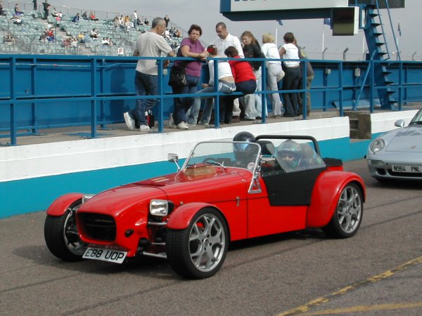
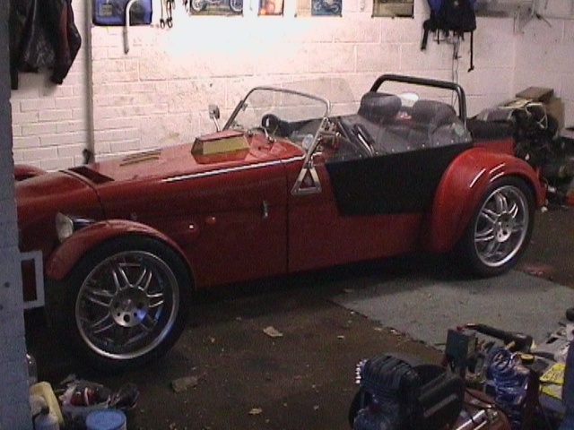 ready
and waiting for some dry hot track!
ready
and waiting for some dry hot track!
 hmmmmm...!
You'll have to watch Comic Strip's 'The Yob' to get the other meaning to this!!
hmmmmm...!
You'll have to watch Comic Strip's 'The Yob' to get the other meaning to this!!
 camera attached to side of roll bar looking over rear arch, Jan 6th 2003,
-2°C!!
camera attached to side of roll bar looking over rear arch, Jan 6th 2003,
-2°C!!
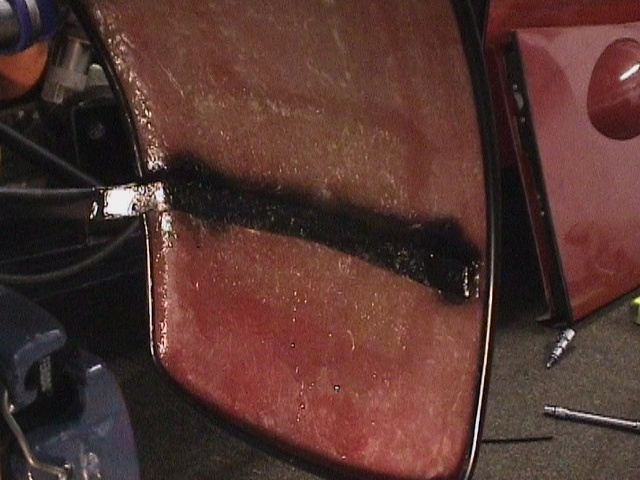
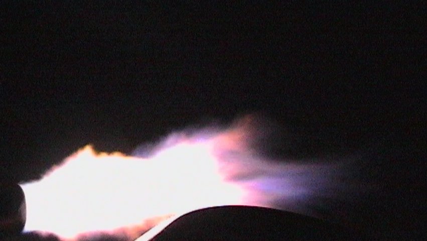 the over run 'burn' can wrap itself around the rear wheel?!!!
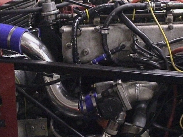
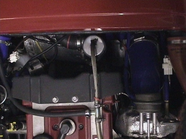
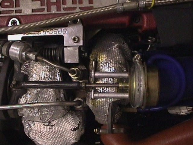
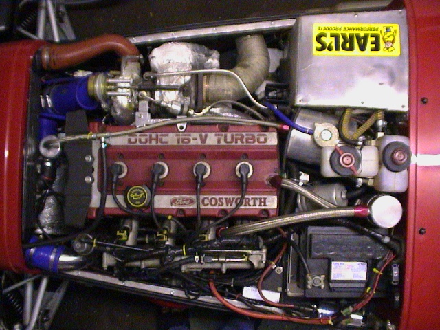 current engine installation
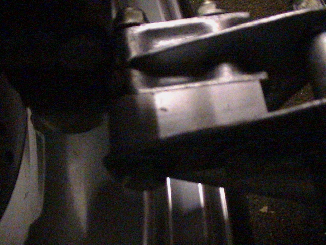 lower ball joint moved back 22mm to lighten steering
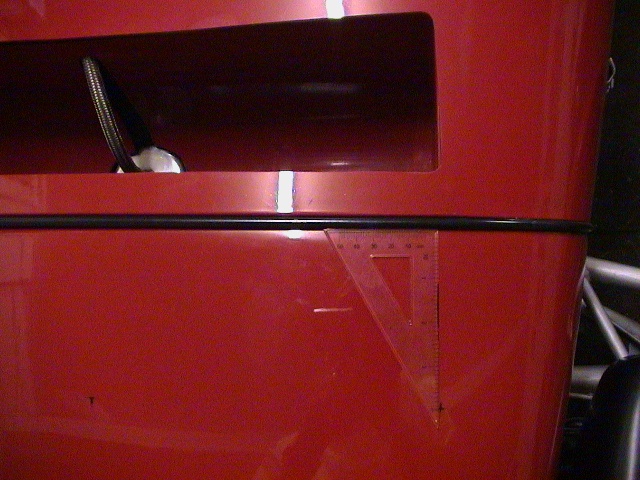 draw a line straight down from bonnet
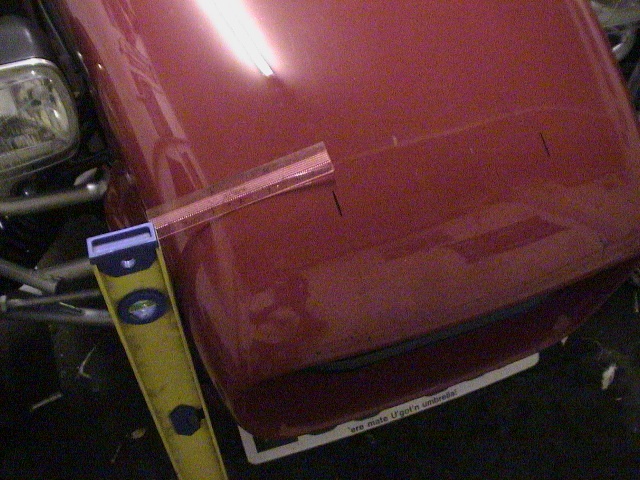 used a spirit level to mark
6 inches in from sides
used a spirit level to mark
6 inches in from sides
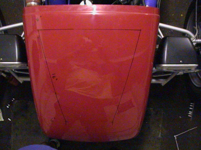 16" from corners of
intercooler to intersect with 6" width.
16" from corners of
intercooler to intersect with 6" width.
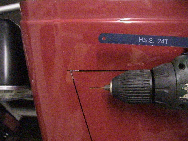 1mm chain drill 3 slots for
the hacksaw blade
1mm chain drill 3 slots for
the hacksaw blade
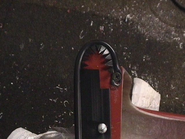
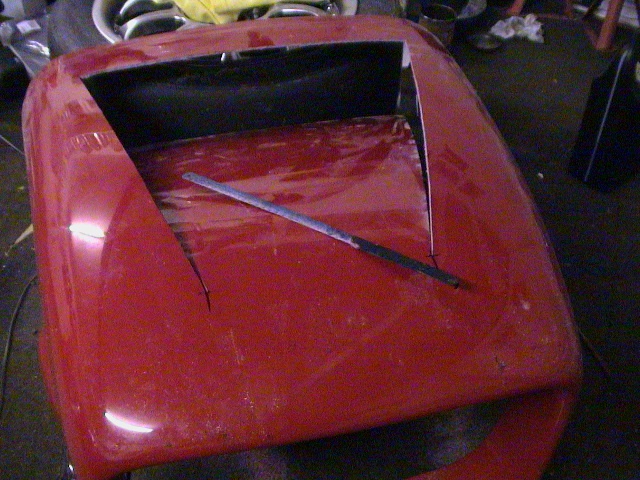 24 tpi blade used to cut top
and sides. Note its preferable to drill a 2mm hole at the front end of the slots
to stress relieve and save cracks before bending - if only...!
24 tpi blade used to cut top
and sides. Note its preferable to drill a 2mm hole at the front end of the slots
to stress relieve and save cracks before bending - if only...!
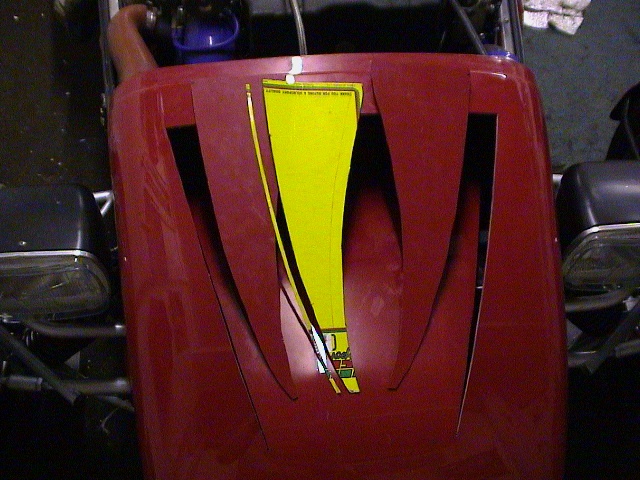 with the flap wedged under
the intercooler a cardboard template can be made for the sides. Lines can be
drawn from the outside allowing 4mm for the thickness of the fibre-glass and 1/2
inch on the bottom for inner bonding.
with the flap wedged under
the intercooler a cardboard template can be made for the sides. Lines can be
drawn from the outside allowing 4mm for the thickness of the fibre-glass and 1/2
inch on the bottom for inner bonding.
 side plates taped in
position and made from colour matched Dax intercooler separator plate!
side plates taped in
position and made from colour matched Dax intercooler separator plate!
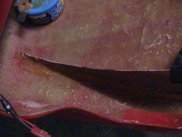 P40 used for speed, but
would have been better left overnight with HV350 for flexibility, i.e. wouldn't
have ended up with gaps at the base of the side plates!
P40 used for speed, but
would have been better left overnight with HV350 for flexibility, i.e. wouldn't
have ended up with gaps at the base of the side plates!
 match paint used to finish
cut edges and section of pipe insulation foam used as air deflector and gap
filler
match paint used to finish
cut edges and section of pipe insulation foam used as air deflector and gap
filler
 extra air flow is worth some
10°C to 20°C reduction in water temperature at speed and 10 reduction in Air
Charge Temperature under hard acceleration
extra air flow is worth some
10°C to 20°C reduction in water temperature at speed and 10 reduction in Air
Charge Temperature under hard acceleration
 engine cutting out on long or successive right handers meant flipping the tank
round so that the outlet is on the LHS. A new ali tube would have probably
easier but none was to hand so I cut a 5inch disc around the outlet tube and
Graham's excellent TIG welding was totally leak free!
engine cutting out on long or successive right handers meant flipping the tank
round so that the outlet is on the LHS. A new ali tube would have probably
easier but none was to hand so I cut a 5inch disc around the outlet tube and
Graham's excellent TIG welding was totally leak free!
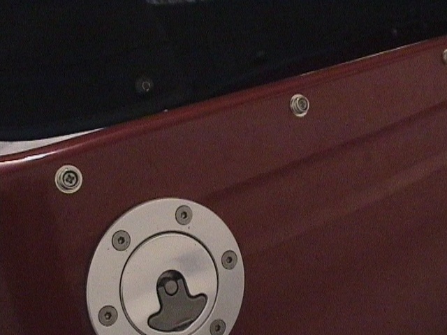
 moving the vent pipe from front to rear allows the tank to fully fill with the
filler cap on the RHS. With the filler pipe further from the back of the car the
station pump nozzle can also be fully inserted with full fuel flow fill-ups now
possible
moving the vent pipe from front to rear allows the tank to fully fill with the
filler cap on the RHS. With the filler pipe further from the back of the car the
station pump nozzle can also be fully inserted with full fuel flow fill-ups now
possible
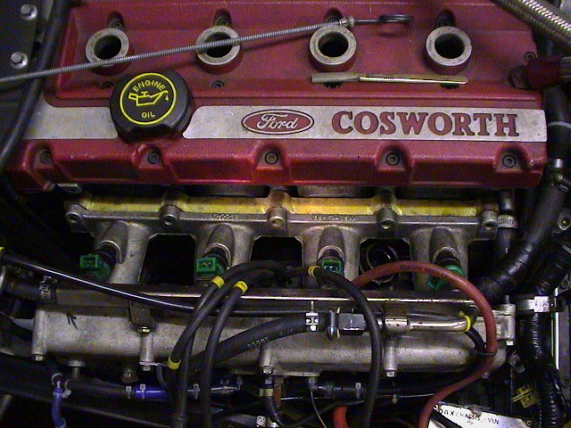 Phenolic resin spacer
between the head and inlet plenum
Phenolic resin spacer
between the head and inlet plenum
 offset plenum requires an
enlarged bulge for the TB, but the 'short fat' Sierra 2.3/2.8 (Fram
PH2854) filter can be removed without disturbing the Throttle body.
offset plenum requires an
enlarged bulge for the TB, but the 'short fat' Sierra 2.3/2.8 (Fram
PH2854) filter can be removed without disturbing the Throttle body.
 engine fully warmed up after a hard run. ACT readings (ie plenum wall) taken
with the bonnet off
engine fully warmed up after a hard run. ACT readings (ie plenum wall) taken
with the bonnet off
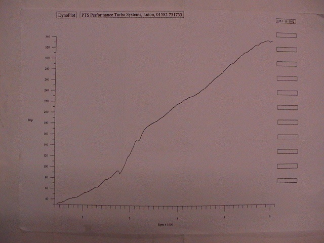 1 off run at PTS rolling
road shoot out running with spacer
1 off run at PTS rolling
road shoot out running with spacer
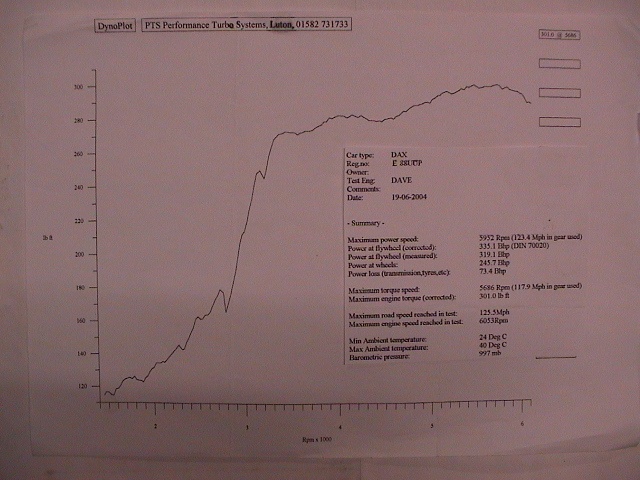 comment from tester was
waste gate not opening very far!
comment from tester was
waste gate not opening very far!