Map Reading & Compass Bearing
Introduction
What is a map?
A topographical map a mathematical determined presentation of a portion of the earth's surface. Symbols, lines, colours and form on the map depicts the manmade and natural features on the real ground.
Why are maps important?
A map provides comprehensive information on the distance between, existence and location of, ground features such as routes of travels and communication, populated places and extent of vegetation cover. It supplies information on the geographical situation of a particular area. It also indicates variation in landforms and heights of ground features.
Map reading covered the ability to interpret the symbols shown on the map and to understand the information given in pictorial or written form, but it must also comprise a true understanding of the ground portrayed and an appreciation of the reality and the value of the particular map being used.
Distance Measurement
Scale of maps
All maps carry graphic liner scales from which any horizontal distance on the map may be measured in kilometers and meters, miles it yards, or using both.
A Liner map scale is always in the form shown in Fig 2.1
Fig 2.1: Linear Map Scale
Measuring a straight line distance
Measure the distance between any 2 points using a piece of paper.
Place one end of the paper against one of the major division so that anther end lies against the sub-division to the left. See Fig 2.2
Total distance is the sum of major division and sub-division to the left of the zero.
Fig 2.2: Scaling a road distance off a map
Measuring a curved distance
Consider the road as a number of straight section
Using a piece of thread, lay the thread along the distance and follow along the curved distance
Mark both ends with a mark
Total distance is the distance of the 2 points marked
Pacing
The skill of knowing how far you traveled is called pacing. Pacing is generally based on a unit of 100m.
The most efficient way of determining distance is by step counting:
1) Single step pacing - counting every stride
2) Double step pacing ---- counting every other stride
The Shape of the Ground
Definition of relief
Relief is a general term applied to the shape of the ground on a vertical plane. The representation of relief on a map is the showing of the heights and shapes of the ground above the sea level.
Elements in representation of relief
There are two distinct elements in the representation of relief. These are:
1) Representation of heights
2) Representation of shape
Units of vertical measure
The standard unit of vertical measure for land maps is the meter
Contours
A contours is a line on the map joining points of equal height and the standard method of showing relief on topographical maps. Contouring combines an accurate indication of height with a good indication o shapes, especially when used in conjunction with spot heights.
Contours are shown at a regular vertical interval (i.e. different in height between successive contours), which varies according to the scale of the amp and to the types of country mapped. The contour interval is always states in the lower margin of the map bear the graphical scales. On a 1/50,000 map, with average relief, the contour interval may be 10 or 20 meters (or 50 feets; at 1/250,000 scales it is probably 50 meters (or 200 feets).
Contours are normally drawn as continuous lines( usually brown or similar colour).Every fourth or fifth contour (depending on the vertical interval) is call an "Index Contour", and is shown by a thicker line. Contour values are placed in breaks made in contour lines; they are paced so that they read right way up when looking up the slope.
Interpretation of contours
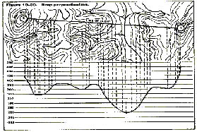
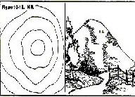
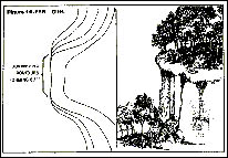
Fig 3.1 shows a perspective view, side view and plan of a hill with its contours. The shape of a contour indicates the shape of the ground. When these contours are further apart, there is a greater distance to gain the height of the vertical interval between contours, and therefore the slopes is gentler than when the contours are closer together. When the contours are an equal distance apart, the slope is uniform.
Figure 3.1 Contours
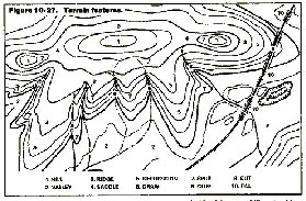
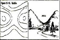
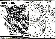
Fig 3.2: Contour Shapes and Features
Fig 3.2 illustrate a number of features as shown by contours and in elevation
Contours are continuous. However far they run, they must in the end return to their starting points. The only exception is when a contour runs into a cliff where the slope is so vertical that there is no room in plane view to show the contours separately. In such a case, the cliff is usually shown by a symbol, and the contours run into it on either side where the slopes permit them to be shown.
When the spacing of contours down a slope gets closer together at the bottom, the slope is convex. Convex slope means short visibility and field of fire: dead ground comes close.
When the spacing if contours get further apart at the bottom the slope is concave. This gives long visibility.
Irregular and closely spaced contours indicates rugged and broken slopes. Smooth contours indicate smooth slopes.
Contours always run up rivers and streams. The sharper the angle at which the contours turns on the stream, the steeper the slopes on the sides.
The correct interpretation of the shapes of the ground from the contours requires practices and experience on the ground. It is essential to study the various features, comparing the map and the ground in each case. First concentrate on the major features (ridges, valleys etc) and then study the minor features (variation of slopes, etc). With practice it should be possible to build up a mental picture of the shape of the ground from the study of the map only, and then to prove it by checking the ground.
Map References
Grid Reference
General Principle
A grid is a rectangle system if lines superimposed on a map, within which any point can be defined and located by reference to the lines enclosing the squares within which the points falls.
Each grid has a number at the edge of the map. The vertical lines numbering from west to east are known as "easting" and the horizontal lines numbering from the south to north are known as "northings".
| 34 |
� |
� |
� |
� |
� |
| 33 |
� |
� |
� |
� |
� |
| 32 |
� |
� |
� |
� |
� |
| 31 |
� |
� |
� |
� |
� |
| � |
72 |
73 |
74 |
75 |
76 |
Fig 4.1: Grid Squares 1
Fig 4.1 illustrates a part of a typical grid system with the given eastings of 72 to 76 units and northing of 31 to 34 units. A and B are two points on the map of which grid reference are required.
Grid references are always given with the eastings value first followed by the northing value; the grid reference of the intersection of the easting line 74 with northing line 33 is therefore 7433.
When giving a grid reference to a square, the reference is always to the southwest corner of the square. Thus the reference to the square in which A falls in Fig 4.1 is 7433. Similarly, B falls in square 7632.
Grid reference with a square (6/8 fig gird reference)
To provide an accurate grid reference to a point of details it is necessary to break up the grid square shown on the map into ten subdivision in each direction as shown in Fig 4.2. This shows the details within the square 7632 containing the points B that is a bridge.
The center point of this bridge is in the small square whose southwest corner id 7/10 east of easting 76 and also 7/10 north of northing 32. Its easting is thus 76.7 and is northing 32.7 units. Omitting the decimal points, the grid reference is thus written as 767327.
The two other bridges within the squares are at 761327 and 764324. similarly the inn is at 765327 and the halt is at 760323.
Should it be necessary to indicate a position even more accurately, the same method of estimation may be extended another stage by dividing each of the small square again into further tenths and by adding a fourth figure to each d the easting and northings.
The fourth figure represent one hundredth of the unit. The reference to the halt in Fig 4.2 could be written as 76073235, but such a reference is only required when a six figure reference is not precise enough to defined the point without any doubt.
Important points to remember are:
1) All the easting figures are always given before the northing figures, i.e, the first half of any grid reference is the easting and the second half is the northing.
2) Grid reference figures are always given to the reference lines west and south of the point. The six-figure reference to the halt is thus 760323 and NOT 761324.
Direction
Describing Direction
The point of the compass
North, south, east and west are the four cardinal points of the compass. There are in all 32 points of the compass but only 16 of them are normally used in map reading for the description of the direction. These are the four cardinal and the twelve intermediate points shown in Fig 5.1
Fig 5.1: The points of the compass
In Fig 5.1 the letter, N, S, E and W stand for North, south, east and west respectively. In the intermediate points these letter are combined, e.g SE is southeast.
Bearings
A bearing is an angle, measured clockwise that a line makes with a fixed zero line. The zero line is always the north, unless some other zero line is stated. If one stands at the point P, and says the bearing of A is 40o, it means that the line PA makes an angle of 40o with the North Line, see Fig 5.2(a). If one says that the bearing of a is 10o form a zero line PB, its means that the angle between PA and PB is 10o, ,measured clockwise, see Fig 5.2(b).
Fig 5.2: Bearing
The essential point to remember is that bearing are always measured clockwise form the zero line, Fig 5.3 emphasizes how the angle of the two bearing is always measured clockwise.
Fig 5.3: Bearing
Back Bearing
A bearing gives the direction of a line from the point of observation P to a point A. A back bearing gives the direction from the point A back to the point of observation P.
Compass
Usage of Compass - The compass is a vital aid to orienteering. It can help you to locate where you are on a map and assist you to fond your way.
The parts of a Silva Compass
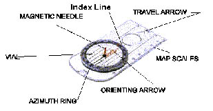
A Silva Compass has three main parts to it. These are:
A) The Compass Itself: This refer to the magnetic needle, the red end of which is North-seeking. So, when the compass is held flat , it swing round the Magnetic North.
B) Dial: The see through plastic case around the compass needle, which cam be rotated. When you rotate the dial, the red line (Orienteering Line or North South Lines) and the red arrow (Orienting Arrow), which are at the bottom of the dial also rotates.
C) Base Plate: The see through plastic on which the dial and compass sit. Along the sides of the base plate are measurement scales which can be used as a ruler to measure the distance on the map. The most important thing on the base plate is the Direction of Travel Arrow. When the arrow meets the dial, there is a little black line on the edge of the dial, which does not move when you rotate the dial. Thus line is called the Index Pointer.
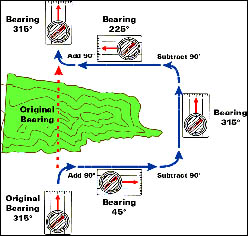
Fig 5.4 illustrate that the different between a bearing and its back bearing 180o. Therefore, given the bearing, to find the back bearing add 180 o, if the bearing is more than 180 o subtract 180 o.
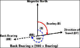
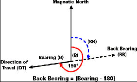
Fig 5.4 Back Bearing
Example:
Forward bearing Back Bearing
40 o 40 o + 180 o = 220 o
280 o 280 o - 180 o = 100 o
True, Magnetic and Grid North
Definition of North
There are three types of North:
1) True North
2) Grid North - Grid North is the northern direction of the north-south grid lines on the map. The grid lines on a map provided the most useful and normal reference for measuring bearing on a map; such bearings measured from the Grid North are called grid bearings. These are the grid bearings most commonly used in map reading.
3) Magnetic North - Magnetic North is the direction in which a compass needle points when free from error or disturbance. This needle is to the magnetic pole, which differs from the North Pole; its position varies slightly form year to year. Bearing measured from the magnetic north are called magnetic bearing; these are the bearings read on a magnetic compass, subject to its individual error.
Taking a map bearing from a map
To read a map bearing from A to B, place the compass with the long side on the line AB and with the line of travel arrow pointing towards B. Then turn the graduated circle and base plate so that the arrow on the base plate points towards grid north and the lines are parallel to the north-south gird lines. The gird bearing of B from A is then read off at the point where the tail of the line of travel arrow cuts the graduation on the circle.
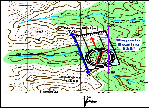
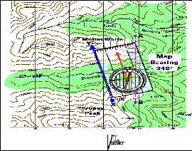
Fig 5.5 Silva Compass set on a map
Taking a field bearing
Hold the compass horizontally and point the direction of travel arrow at the object
While keeping the compass in this position, turn the graduated circle so that the orienteering arrow on the base plate corresponds with the north (red) end of the needle.
The field bearing is the read off at the direction of travel line.
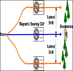
Walking on a bearing
Look straight ahead in the direction of a set bearing.
Pick a landmark at a reasonable distance away.
Hold the compass in front of you as you walk in the direction of the line of travel arrow.
Keep the compass needle and the orienteering arrow coincident.
Take the easiest route to the landmark without looking at the compass.
On reaching the landmark, repeat the sighting procedures and so until you reach you destination.
The stick shadow
A stick shadow can give you an accurate indication of direction.
Push a stick vertically into the ground and mark where the tip of its shadow falls.
After the shadow has moved several inches, mark the tip again.
A line connecting the two marks will run east and west, east being in the direction of the second mark (see Fig 5.6).
Another line perpendicular to the first will run north and south.
Fig 5.6: Telling direction from a stick shadow
Map Setting and Position Finding
Setting a map
Introduction
"Setting" a map, means turning the map so that the directions to details on the ground corresponds to the same directions on the map/ This is also called "orienting" the map,
When in doubt about where you are, or in which direction you should turn, and when moving over a complex route, it is necessary to orient the map and hold the map correctly oriented.
Two basic method of setting map:
a) By inspection of the surrounding detail.
b) By setting on the North point.
Setting a map by inspection
The simplest and the quickest provided you have some ideas of your position.
If you are on a straight road, line up the road map with the road on the ground, pointing it in the right direction: at a crossroad, map can be set similarly.
If you are not on a road, or are on a road which is not straight and you cannot identify the bit is necessary to locate other objects such as a particular house, church, etc whose direction you can check in relation to your own approximate position.
In open hilly ground, you may have to rely on the shape of the ground and on the corresponding positions of the contours. If you are on a ridge or spur, set the map so that the features corresponds with the contours.
Setting a map by this method is not precise, but the map can be set quickly and quite accurately enough for you to be sure of your direction.
Setting a map by the North point
If you cannot immediately recognize sufficient detail around you to enable you to set the map as describe above, the simplest approximate method of setting is by the sun, if is visible.
To set the map more precisely, a compass must be used. With a Silva Compass, set the degree to zero, with the direction of travel arrow coincide with the north direction of a grid line. Then rotate the map with the compass on it until the compass needle coincides with the north points on the dial (0).
Finding your position
General
If you don't know your position, the first essential step is to orient the map by one of the methods described before.
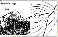
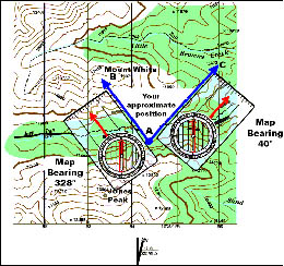
Fig 6.1 Resection
Finding position from distance detail (Resection)
If there is no local detail, and if the contours are not sufficiently close or shaped to give you a reliable indication of position, your position can only be determined from distant objects such as hill tops, corners of woods, or other natural features. Select three points around you so that your position is within the triangle by the points.
If you have a means if marking the line of sight from each point accurately on your map, while keeping it correctly oriented, mark these lines on the map. If your map is correctly set, these lines will meet at a pint which is your position, or least they will make a small triangle within which your position falls. Check form a fourth pint if available.
If you don't know your position, the first essential step is to orient the map by one of the methods described before.
Finding the position of a distant object
It is necessary to locate the position of a distant object:
a) To locate the position on the map of an object visible on the ground.
b) To find on the ground an object whose position is known on the map.
To solve the first problem, used a compass. If the object is visible but its map position is unknown, take up a position, which you can identify on the map, and take the field bearing of the object. Convert this into the map bearing by placing it on the map. Your object will then lie on this line.
Orient your map and study it along the lone, comparing it with the features on the ground: determine the approximate distance at which your object lies in relation to those features Assuming your object is marked on the map, you should then be able to locate it on the map. If it is not marked on the map, identify objects close to it, which are marked, and determine its position by reference to these objects.
To solve the second problem, draw on the map the lone of bearing from your position to the object. Measure the map bearing and convert it to field bearing. With your compass, look along this bearing and identify the point on the ground.
Maintenance of Maps and Compass
Maintenance of compass
Do not bundle compasses together.
Do not swing the compass about.
Do not place compass near metallic or magnetic objects.
Maintenance of Maps
Waterproofing a map:
a) Get a large, zip-lock bag and a few section of sturdy, waterproof tape.
b) Wrap the map carefully in the plastic bag and seal it with the adhesive tape.
c) The map should fit exactly into the bag and not allowed to slide within the bag. If a bag bigger than the map is being used, the sliding of the map can be avoided by further securing the excess of the plastic with the tape.
Maps should be folded according to the grid lines.
It is necessary o fold the map because
a) It prevent a map from being crumpled in case of strong wind.
b) It makes it more convenient for carrying.
c) It allows the user to focus on the desired portion of the entire map.
Map and compass tips
A) At trailhead, where you know your position, identify prominent landmarks and orient the map.
B) As you like, pause frequently to consult the map or compass and establish your whereabouts. But do not stumble along looking at them.
D) Each time you fix your location, check the map for features yet to comes so that you will recognized them. As you walk, watch for these features.
If you are lost
1) Try to retract your steps to the place where you knew where you are.
2) If step 1 does not work, orient your map. On the map, try to spot the last point where you confirmed your location.
3) On the map, and in your surroundings, look for identifiable landmarks such as prominent peaks or ridges.
4) If it still does not work, mark the spot where you are with a couple of rocks or a broken branch, so that you will recognized "home-base" again.
5) Then keeping your gear with you, walk in one direction for a hundred feets or so. If thing do not look familiar, return to "home-base" and walk in another direction.
6) Continued to take straight-line excursions along the radius from "home-base". More often than not, you will intercept the trail or spot familiar ground.
7) If not, resign yourself to staying put for a while, perhaps overnight. Find a protected spot and make a shelter. If is safe to do so, build a fire for warmth and for signal.
8) Mark the area to help searchers, using articles like clothing, a brightly colored tarps or poncho.
9) Ration your food.