| WIDE
FREQUENCY COVERAGE |
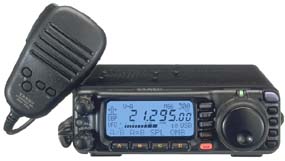
The FT-100 is the smallest
transceiver in the world providing such wide frequency coverage. Providing
transceiver coverage of the HF, 50 MHz, 144 MHz, and 430 MHz amateur bands
on SSB, CW, AM, FM, AFSK Teletype, and Packet, the FT-100 also includes
receive coverage of
I00KHz through 970 MHz, so you can
monitor public safety, weather broadcast, AM and FM broadcast, and TV audio
transmissions, in addition to all the action on the ham bands. All this
from a rugged compact case measuring just 160 (W) x 54 (H) x 205 (D) mm
(6.3" x 2.2" x 8.0")! |
| HIGH-PERFORMANCE
RECEIVER DESIGN |
| Building on the acclaimed
performance of the FT-1000D, FT-1000MP, and FT-847, Yaesu's engineers have
crafted the FT-100's front end for a very low noise floor and wide dynamic
range. Utilising an up-conversion architecture for HF with a 68.985 MHz
first IF, the FT-100 features a double-conversion superheterodyne system
(triple-conversion on FM) with the 2nd IF at 11.705 MHz. The first mixer
is a low-noise, high-intercept design using SST310 JFETs in a doubly-balanced
configuration. On 144/430 MHz, the very- low-noise GaAs MES FET SGM2016
preamplifier is followed by an HSB88 diode-ring mixer, yielding the excellent
Noise Figure required for weak-signal work. The front-end devices are individually
selected and matched, ensuring a high level of performance consistency
as units are manufactured. |
| DIRECT
DIGITAL SYNTHESISER |
| To ensure the dual goals
of low receiver noise floor and wide dynamic range, Yaesu's engineers utilise
an AD9850 Direct Digital Synthesiser (DDS) for the main local oscillator
of the FT-100. Providing fast locktime and excellent Carrier-to-Noise (C/N)
ratio, the DDS also yields tuning steps as small as 1.25 Hz, for silky-smooth
action indistinguishable from an analogue VFO system. The PLL circuits
in the FT-100 feature a low-noise custom J-FET device (FQ7925), thus enhancing
system performance. |
| ADVANCED
FEATURES FOR ACTIVE DXERS |
| * IF Shift : Use the
IF SHIFT feature to vary the center frequency of the IF passband, so as
to eliminate interference above or below the current operating frequency.
* IF Noise Blanker : Optimised for
use in the mobile environment, the FT-100 includes an effective IF Noise
Blanker specially designed for suppression of ignition and other pulse-type
noises. The Noise Blanker's threshold is adjustable via the MENU system.
* Intercept Point Optimisation (IPO):
For reception on the lower frequencies, where very low Noise Figure is
not required, the IPO feature causes the RF preamplifier to be bypassed,
allowing direct signal input to the first mixer. An input attenuator is
also available, for reception under extremely noisy conditions.
* Adjustable AGC : The Automatic Gain
Control (AGC) circuitry of the FT-100's receiver may be adjusted, via the
MENU, for SLOW or FAST receiver recovery times. A convenient "AUTO" setting
programs "FAST" AGC for CW, and "SLOW" for voice modes.
* Clarifier (RIT) : For split-frequency
pile-ups or to follow drifting signals, the Clarifier control provides
upto ±9.99 kHz of adjustment of the receiver's frequency, without
changing the transmitter frequency. For wider-split pile-ups, the "SPLIT"
mode allows you to use VFO-A and VFO-B separately, too.
* RF Gain Control : For noise reduction
and/or variation of the AGC system threshold, the MENU allows the front
panel's Squelch control to be switched to operate as an "RF Gain" control.
* VOX : For hands-free voice operation,
the VOX system includes MENU adjustments for both VOX Gain and Delay. A
separate setting is also provided for receiver recovery in the CW mode. |
| ONE-TOUCH
SCROLLING FRONT PANEL |
| The A, B, C, and D keys
below the display provide access to many control functions for the FT-100,
including VFO selection, Memory Channel loading, Repeater Shifts and Tones,and
Filterselection. |
| MULTI-PURPOSE
MEMORY SYSTEM |
| The FT-100 provides 6
Memory Groups of 50 Channels each, for a total of 300 "Regular" memories.
In addition, you get 20 "Split Frequency" memories, 5 Quick Memory Bank
(QMB) memories, 4 "Home" Channel memories, and 20 Band-Limit memories,
for a grand total of 349 Memory Channels! Use the QMB or Home channels
for Quick QSY to a favourite frequency, and use the Split memories for
DX-pedition pileups or 7MHz SSB work. |
| HIGH
RESOLUTION DOT-MATRIX DISPLAY |
| The large (70 mm x 30
mm) blue LCD dot-matrix display provides easy-to-read indication of many
operating functions, including frequency, RX and TX metering, operating
functions, status icons, and the Spectrum Scope bar-graph. And to set the
illumination level precisely to the brightness you want, the MENU provides
a "Dimmer" feature with 64 degrees of illumination. |
| OPTIONAL
REMOTE MOUNTING KIT |
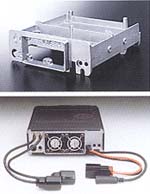
| For mobile operation
where mounting space is very limited, the optional YSK-100 Separation Kit
allows the front panel to be remotely mounted on your dashboard, with the
transceiver stashed away in available space. Data is transferred between
units at a lightning-fast rate of 62,500 bps, for seamless remote operation. |
| AND
SO MUCH MORE... |
| * Two Antenna Jacks (HF/50
MHz, 144/430 MHz) using Type M (UHF) connectors
* Three Programmable Microphone Keys
(ACC, P1, and P2) for easy feature access
* Easy Linear Amplifier interface
* AF Speech Processor
* Automatic Power-Off (APO) feature
turns radio off after 1/2/3 hours to limit battery drain
* Time-Out Timer (TOT) limits "stuck
mic" interference potential
* Dual VFOs for quick QSY
* Peak-Hold metering of Signal Strength,
Power Output, and relative SWR/ALC
* Easy-to-use MENU system for custom
"Set and Forget" configurations. |
|
| RUGGED,
HIGH-OUTPUT TRANSMITTER DESIGN |
 The
FT-100's power amplifier section utilises MOSFET devices, providing low
noise, low distortion, and high reliability. The HF/50 MHz amplifier provides
100 Watts of output, while the VHF/UHF section generates 50 Watts of power
on 144 MHz, and 20 Watts on 430 MHz. Reliability is assured thanks to the
extensive cooling system, featuring twin cooling fans and an aluminium
diecast chassis. The
FT-100's power amplifier section utilises MOSFET devices, providing low
noise, low distortion, and high reliability. The HF/50 MHz amplifier provides
100 Watts of output, while the VHF/UHF section generates 50 Watts of power
on 144 MHz, and 20 Watts on 430 MHz. Reliability is assured thanks to the
extensive cooling system, featuring twin cooling fans and an aluminium
diecast chassis. |
| ENHANCED
TRANSCEIVER PERFORMANCE THROUGH DIGITAL SIGNAL PROCESSING |
| For superior interference
rejection and transmitter "talk power," the FT-100's DSP circuitry enhances
both sides of the communications circuit. The FT-100 DSP Unit features
a 24-bit high-tech D/A chip for signal processing.
* Digital Dual Bandpass Filter : Providing
"brick wall" audio selectivity for voice modes, the Bandpass filter allows
independent High-Pass and Low-Pass Filter adjustments, with cut-off frequencies
of 100 Hz - 1000 Hz (HPF) and 1000 Hz - 6000 Hz (LPF). On CW, the Bandpass
filter becomes an Audio Peaking Filter with available bandwidths of 60/120/240
Hz.
* Noise Reduction Filter: BuiIding
on the highly-successful Noise Reduction feature of the FT-920, the FT-100's
DSP utilises multi-parameter analysis for efficient processing and reduction
of incoming noise. A total of 16 Noise Reduction settings are available
for best results under changing conditions.
* Automatic Seeking Notch Filter: For
removal of annoying carriers or heterodynes, the DSP Notch Filter will
identify and suppress one or more such signals automatically, thus improving
copy and reducing operator fatigue.
* Microphone Equaliser : To match the
FT-100's transmitter audio response to the waveform produced by your voice
and the microphone in use, the DSP system includes a three-position Mic
Equaliser circuit. The result is increased "talk power" as extraneous frequencies
are suppressed, allowing all available power to be concentrated into your
voice's pattern. |
| CW
OPERATING FLEXIBILITY |
| * Built-in Electronic
Keyer: The FT-100's built-in Electronic Keyer includes Dot : Space and
Dash : Space weight adjustments.
* CW Message Memory : For repetitive
"CQ DX" or "CQ TEST" messages, the FT-100 includes a 50-character CW Message
register.
* CW Full Break-in (QSK) : Both "Full
QSK" and "Semi-Break-In" CW modes are available, with excellent keyed waveforms
in both modes.
* CW "Reverse" Reception : When interference
is encountered in the CW mode, the "Reverse" feature allows the injected
sideband to be changed between "USB" and "LSB" by a simple press of the
"MODE" switch on the front panel.
* CW Pitch/Sidetone Control : The CW
PITCH control allows the transmitted signal to be offset 400/500/600/700/800
Hz from "zero beat" with the receive frequency. This adjustment simultaneously
varies the center frequency of the RX passband (including the DSP BPF),
as well as the CW Sidetone's pitch. The sidetone therefore serves as a
"Spot" signal during tuning.
* Optional CW Filters : Available options
for the FT-100 include the 500 Hz XF-117C and 300 Hz XF-117CN crystal filters.
both of which may be installed at the same time. |
| MULTI
FUNCTION "SELECT" KNOB |
| The front panel's SELECT
knob acts as a Quick-QSY dial for tuning, with independent steps on different
bands and modes. The SELECT knob is also used for Memory Channel and MENU
item selection, as well as CLARIFIER tuning and IF SHIFT adjustment. |
| EASY
DATA-MODE SETUP! |
| For operation on a wide
variety of data modes, including 1200/9600 bps FM packet, RTTY (AFSK),
or SSTV, the rear- panel's 6-pin mini-DIN connector provides easy access
to Data I/O lines, plus PTT and Ground. |
| VERSATILE
SCANNING MODES |
| * VFO Scan: Scan up or
down the band in the VFO mode.
* Memory Scan : Scan within the current
Memory Group, or scan all the memories.
* Programmable Memory Scan (PMS): Use
PMS to scan within band limits set by the special PMS memories.
*QMB Scan : When operating on the QMB
channels, you can also elect to scan just those memories. During
scanning operation, the FT-100 can be set up to Stop completely when a
signal is encountered; to Hold until the incoming transmission ceases:
or to Resume after a delay of 1 to 10 seconds. |
| LEADING-EDGE
FEATURES FOR VHF/UHF OPERATORS |
| * Automatic Repeater
Shift: On the 144 MHz and 430 MHz bands, the FT-100 will automatically
activate the repeater shift appropriate for the part of the band in which
you are working.
* CTCSS/DCS Tone Systems : For repeater
access, a CTCSS Encoder is built into the FT-100 (FTS-27 Decoder optional),
and for advanced systems a 104-code Digital Code Squelch system provides
improved immunity from false decoding.
* SmartSearch: When visiting a new
city, use the Smart Search system to scan the FM band for activity. When
busy channels are found, they will be automatically loaded into a special
Smart Search Memory Bank, for easy recall.
* Spectrum Scope: If you have to be
away from your radio for a few minutes, turn on the Spectrum Scope to keep
watch on band activity. The Spectrum Scope will create a bar-graph display
of activity an 15 channels above and below your current operating frequency.
* ARTS(Auto-Range Transponder System):
During Search-and-Rescue operations, the ARTS feature will notify you
if a field station (for example, a hand-held unit) has gone out of communications
range, so you can instruct them to move to a better location. |
|
|
|
SPECIFICATIONS
|
| GENERAL |
|
Frequency Ranges:RX:
|
100
kHz - 970 MHz |
|
TX:
|
160-6 Meters |
|
2 Meters |
|
70 Centimetres
(Amateur Bands Only) |
| Emission
Modes: |
A1 (CW), A3
(AM), A3J (LSB/USB), F1 (9600 bps Packet), F2 (1200 bps Packet), F3 (FM) |
| Synthesiser
Steps (Min.): |
1.25 Hz (CW/SSB),
100 Hz (AM), 100 Hz (FM), 1 kHz (FM) |
| Antenna
Impedance: |
50
Ohm, Unbalanced |
| Operating
Temp. Range: |
-10oC
to +60oC (14oF to 122oF) |
| Frequency
Stability: |
Better than
±4 ppm (-10oC to +50oC) (SSB/CW/AM) |
|
Better than
±(1 kHz +4ppm) (FM) |
| Power
Requirements: |
DC 13.8V ±10%,
Negative Ground |
| Current
Consumption: |
Receive (Squelched):
1.2A |
|
Receive (Max.
Audio): 1.6A |
|
Transmit:
22A @ 100W RF Output |
| Case
Size: |
160(W) x 54(H)
x 205(D) mm |
|
(6.3" x 2.2"
x 8.0") WHD |
|
Weight:
|
3 kg (6.6
lb.) |
|
| TRANSMITTER |
|
RF Power Output: 160-6m:
|
100
Watts (25 Watts AM carrier) |
| 2m: |
50
Watts (12.5 Watts AM carrier) |
| 70cm: |
20
Watts (5 Watts AM carrier) |
|
Modulation Types:
SSB:
|
Balanced
Modulator |
| FM: |
Variable
Reactance |
| AM: |
Early
Stage (Low Level) |
| FM
Maximum Deviation: |
±5
kHz (±2.5 kHz on FM-N) |
| Spurious
Radiation: Harmonics: |
At
least 40 dB down (1.8-29.7 MHz) |
|
At
least 60 dB down (50/144/430 MHz) |
| Non-harmonic: |
At
least 50 dB down (1.8-29.7 MHz) |
|
At
least 60 dB down (50/144/430 MHz) |
| Carrier
Suppression: |
At
least 40 dB |
| Opp.
Sideband Suppression: |
At
least 50 dB |
| SSB
Frequency Response: |
400
Hz - 2600 Hz (-6 dB) |
| Microphone
Impedance: |
200
Ohm - 10 K Ohm (Supplied Microphone: 2 K Ohm) |
| RECEIVER |
| Sensitivity: |
SSB/CW |
AM-N |
FM |
| 150kHz-250kHz
(IPO off): |
5uV |
40uV |
- |
| 250kHz-1.8MHz
(IPO off): |
4uV |
40uV |
- |
| 1.8-28 MHz
(IPO off): |
0.25uV |
2uV |
- |
| 28-30 MHz: |
0.25uV |
2uV |
0.50uV |
| 50-54 MHz: |
0.20uV |
2uV |
0.50uV |
| 144/430 MHz: |
0.125uV |
2uV |
0.20uV |
|
| Above
specifications are worst-case |
| SSB/CW/AM-N
figures are for 10 dB S/N, 12 dB SINAD on FM |
| Squelch Sensitivity
: |
SSB/CW/AM |
FM |
| 1.8-28 MHz
: |
2.5uV |
- |
| 28-30 MHz
: |
2.5uV |
0.32uV |
| 50-54 MHz
: |
1.12uV |
0.20uV |
| 144/430 MHz
: |
0.8uV |
0.16uV |
|
| Intermediate
Frequencies: 1st IF: |
68.985
MHz (SSB/CW/FM/Digital) |
|
67.980
MHz (W-FM) |
| 2nd
IF: |
11.705
MHz (SSB/CW/FM/Digital) |
|
10.700
MHz (W-FM) |
| 3rd
IF: |
455
kHz (FM) |
| Image
Rejection: |
Better
than 70dB (1.8-30 MHz) |
|
Better
than 70dB (50-54 MHz) |
|
Better
then 60dB (144-148 MHz) |
|
Better
then 60dB (430-450 MHz) |
| IF
Rejection: |
Better
than 70dB (1.8-30 MHz) |
|
Better
than 60dB (54-54 MHz) |
|
Better
than 60dB (144-148 MHz) |
|
Better
than 60dB (430-450 MHz) |
| Selectivity
(-6/-60 dB): |
|
| SSB/CW: |
2.2
kHz/5.2 kHz |
| CW |
450
Hz/1.8 kHz (Opt. XF-117C Installed) |
| CW-N |
250
Hz/1.2 kHz (Opt. XF-117CN Installed) |
| AM |
5.2
kHz/18 kHz (Opt. XF-117A Installed) |
| FM |
15
kHz/25 kHz |
| Audio
Output: |
At
least 1.5W into 8 Ohm @ 10% THD |
| Audio
Output Impedance: |
4
- 8 Ohm |
|
|
|
©
2000 Yaesu USA
|