CS 151: Digital Design
Computer Lab 1
Using CAD Schematic Capture Tools
Objective:
To allow students to draw logic diagrams for simple functions using CAD schematic capture tools.
Tool:
The tool used for this lab demonstration will be Microsoft Office Visio 2003.
Example:
Draw the logic diagram that corresponds to the function F(X,Y,Z) = X'Y + XZ.
How to Start MS Office Visio:
- Select
Start à
All Programs à Microsoft Office à
Microsoft Office Visio 2003.
Microsoft Office Visio window opens.
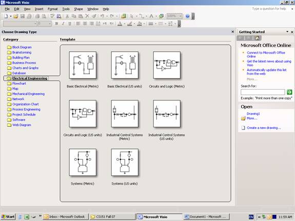
- Select Electrical Engineering folder from the Category column to the left as shown above.
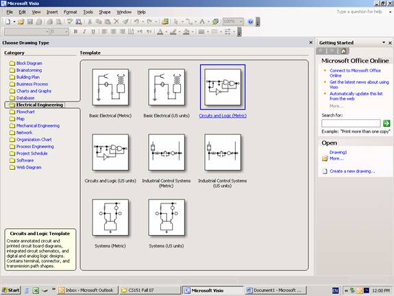
- Select Circuits and Logic (Metric) as shown above.
Drawing 1 window opens.

- The Shapes panel to the left includes most of the needed shapes organized in four different taps:
- Analog and Digital Logic tap: Where you'll find gates like inverters, buffers, AND gates and I/O ports.
- Integrated Circuit Components: That includes basic functional blocks like different decoders and multiplexers.
- Terminals
and Connectors.
- Transmission Paths: This includes objects like junctions and busses.
Note: Many gates, like the OR gate, are not available in this library and can be used by searching for and downloading them using the Search For Shapes textbox at the top left corner of the Shapes Panel.
- Finally, now as you know how to access the tool and are familiar with its environment, to draw the circuit, follow the instructions during the demonstration lab.