|
The Harley Davidson "F"
head engine
|
* The
"F"-head H-D
Relatively
modern for their day, with chain drive, three speed countershaft gearbox,
rear drum brake and lubrication by an engine driven oil pump, the "F" and
"J" H-D motorbikes are interesting restoration objects because of their
high quality and because they still can be used on the road without too
many problems from the Ministry of Transport. Until recently France was
a primary source of these bikes where many of the about 15,000 military
H-D bikes delivered in the First World War had survived.Restoration of
the "F"-head models is not an easy job - some of the essential spare parts
are very difficult to get - and requires a good knowledge of the underlying
technical principles applied in these engines. Great help is to be found
in the following books, which are a "must" for the "F"-head restorer.
* Literature
For
details of the evolution of this model during its years of production,
the book "Inside Harley Davidson, an Engineering History of the Motor Company
from F-heads to Knuckleheads 1903-1945" by Jerry Hatfield, ISBN 0-87938-388-7
(A) can be recommended; the "Motor Repair Manual for the Guidance of the
Motorcycle Repairman" by Harley Davidson (B), is indispensable as regards
the engine overhaul. Unfortunately reprints are difficult to find nowadays.
Mr J.W. Boon
Meppelerweg 3, 7963 RV Ruinen (tel: NL (0)522-471177 - fax. -473433) Netherlands,
just (end 1998) publised a new catalog of parts for Pocket-Valve Models
1915-1929, which he has available .
* Engine
restoration
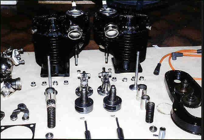
While
restoring complete 1916 and 1918 bikes and a further 1920 engine, and talking
to other owners and restorers about the problems they encountered, many
hints and tips were exchanged and solutions were found which might be of
interest both to other H-D owners and to restorers of other bikes. Most
of the work described in the following recommendations can be done yourself
and, when the use of machine tools is necessary, it is at least possible
to prepare the parts for machining, so that the costs will be lower compared
with having all the work done by a specialist. Moreover when you carry
out assembly yourself, you have a final possibility to check on what has
been done by others; sadly this proves necessary nowadays.
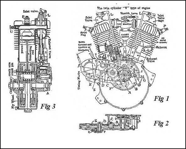
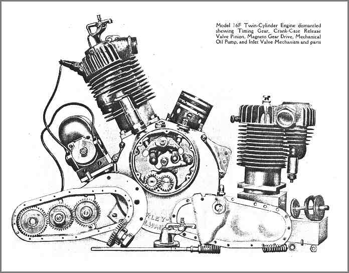
Let us start with the engine overhaul, which is very
well described in book (B). The engine design will be clear from figures
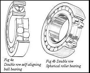
1 to 3 (1917 and later models).When comparing the pre-1916 and later engines,
it was found that until 1916 the sprocket side of the crankshaft was journalled
in a self-aligning double row ball bearing (figure 4a) which, peculiarly
for an American bike, is a millimetre sized bearing (1305-25x62x17mm, max
load: Cr=13800N, Cor=6000N).After 1916 a double row roller bearing of H-D
manufacture was used (see figure 3). According to book (A) the earlier
crank cases, whose left half (sprocket side) has a large diameter bore
because of the large bore of the ball bearing race, were used for so-called
"fast" motors even after 1916, perhaps because the self-aligning bearing
allows the crankshaft to swing or bend at high speeds.For restoration,
it was decided to replace the 1916 self-aligning double row ball bearing
by a double row spherical roller bearing (see figure 4b) (21305-25x62x17mm,
max load Cr=39100N, Cor=25700N), dimensioned to be on the safe side under
operating loads and retaining the self-aligning function.
* Adaptations
The self-aligning
bearing arrangement stimulated me also to adapt the later crankcases to
such an arrangement, not only because of the better support for the crankshaft
but also because of its easier assembly with the crankcases; not the least
consideration was the easier availability and lower cost of bearing assemblies
compared to the loose parts of the original double row roller bearing arrangement.
Looking through the pages of a bearing catalogue, a double row spherical
roller bearing of the size 25x52x18mm was found (22205CC max load: Cr=30500N,
Cor=21600N).Since the sprocket shaft has a diameter of 1" (25.4mm) and
the original outer bearing ring in the crankcase has an outer diameter
of 2" (50.8mm), only very little material needed to be removed from the
shaft (from 25.4 to 25mm) and from the crankcase bore (from 50.8 to 52mm)
to fit this spherical roller bearing! The selected double row spherical
roller bearing is not cheap (about 100 DM in Germany) but, since in most
restorations a new bearing ring and sprocket shaft would otherwise have
to be manufactured, because these are usually either rusted or worn, the
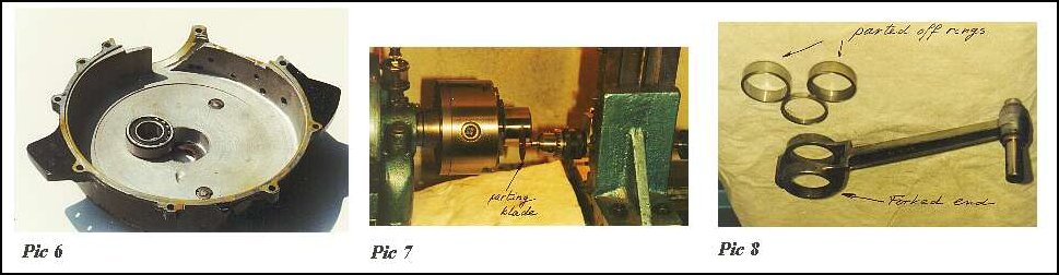
proposed adaptation to fit a standard roller bearing proves cheaper overall.The
work on the sprocket shaft (grinding it down to 25mm) and on the crankcase
(enlarging the bore to 52mm) is relatively straightforward and, when the
work is done in a machining workshop, is not very expensive (picture 6)
. When pressing the bearing into the crankcase it is advisable to insert
a steel washer of 52mm outer diameter behind the bearing in order to allow
the bearing to be pressed out again, in the same way as the original bearing
outer race, if necessary. This washer ring should be of sufficient thickness
so that the bearing when pressed into the crankcase is flush with the inside
of the crankcase.
* Pinion
shaft bearing
The pinion
gear shaft is journalled in a large bronze bearing bush. If a new one is
required do not forget to regrind the shaft which is normally worn unevenly
(thick in the middle, small at either end) from bending of the crankshaft
under load. According to instructions in the above referred to H-D manual
(B), a clearance of 0.002 to 0.003 inch (0.05 to 0.07mm) should be allowed
for the pinion shaft bearing. Experience teaches (fortunately not mine!)
that preferably 0.07mm should be given, to avoid any seizing of the shaft
in the bushing: a perfect alignment of these build-up type crankshafts
can rarely be achieved and therefore more clearance is required.The original
bushing has spiralled oil grooves but, in view of better insight into lubrication
of plain bearings nowadays, it is possible to omit these grooves and recommended
to ensure instead that the lubricating oil supplied from the holes in the
upper part of the bushing is distributed over the entire width of the bushing.
* Crankpin
bearings
Let us
now turn to the crankpin bearings, which have required full replacement
in all my engines. The big end comprises a 1" diameter crankpin, four rows
of 12-1/4" rollers in open ended cages, and bearing rings pressed into
the connecting rods. New crankpins are still available (J.W. Boon) at reasonable
cost, but a supplier for new bearing rings of the correct size could not
be found. (I just see that J.W. Boon has the
rod races in his new 1998 catalog too! ) It
is possible to use H-D "Liberator" bearing rings, intended for the forked
conrod, and to use two of those side by side for the middle conrod. Because
"Liberator" bearing rings are normally sold in sets comprising two narrow
rings for the forked conrod and one wide ring for the middle conrod, two
sets are therefore necessary to rebuild one "F"-head crankshaft. When measuring
the ring diameters it was realized with relief that obviously millimetre
size bearing rings had been used here too. The outer diameter of the rings
is exactly 43mm and corresponds to the outer diameter of needle bearing
inner rings of the size 38x43x20mm (1) and 38x43x30xmm (2), which are readily
available and relatively cheap. The size (1) was used for the single eyed
middle (rear) conrod and size (2) was used to part off the required width
of 9.5mm each for the forked (front) conrod bearing rings (pictures 7 and
8).
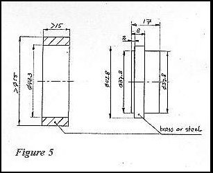
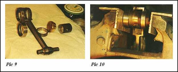
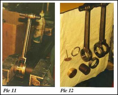
Pressing the bearing rings into the single eyed
conrod is quite straightforward and can be done with a vice. The forked
conrod needs more attention, since all sideward load on the fork should
be avoided. A simple "pressing-tool-set" (see figure 5, a ring and brass
or steel arbor) was manufactured on a lathe so that the new bearing rings
could be pressed into the forked ends from the inside to the outside of
the fork (see pictures 9 and 10 for pressing out the bearing ring and picture
11 for pressing in the bearing ring, picture 12 shows the finished job
and the tools used). Leave enough side clearance for the single-eyed conrod
bearing ring so that oil can reach the rollers when the big-end bearing
is assembled!
In order to keep sufficient clearance for lubrication
it is advised firstly to measure the total width between the flywheels
with the new crank pin in place and then to calculate the width of the
rings to be parted off such that the side clearance of the middle conrod
is about .02" (0.5mm) in the fork and the side clearance of the fork between
the flywheels is 0.006" to 0.012" (0.15 to 0.30mm).
The inner diameter of the rings becomes slightly
smaller than 38mm after the rings have been pressed in but these must be
lapped anyway to achieve the correct inner size of about 38.1mm - crankpin
diameter of 25.4mm + 2x roller diameter of 6.35mm (1/4" rollers) adds up
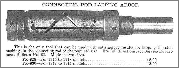
to 38.1mm.You can do the lapping of the inside of the rings yourself if
you have an H-D lapping tool (see picture 13), or you can leave this to
a specialist at reasonable cost.When lapping I used the old rollers to
check whether the correct diameter was almost achieved. Then by lapping
with the finest grinding paste and lapping only very slightly each time,
the fitting diameter for the new rollers was reached.This last lapping
sequence must be done with great care in order not to lap away so much
that after the rollers have been inserted the conrods show sideplay (see
also the H-D lapping instructions in book (B). Altough the use of the HD
lapping tool for lapping 0.1 mm from the big-end roller bushes is not the
correct use of a lapping tool, the necessary grinding equipment is normally
not available for the restorer and it was found that with some care it
is very well possible to achieve good results.
The advantage of using the original 1/4 x 3/8" size
rollers - which are still available, as also are oversize rollers - is
that the original retainers (cages) can still be used; this sometimes proves
problematical when bigger, oversize rollers are used.The retainers must
be checked to avoid any clamping on the rollers, as this would lead to
premature failure of the big-end bearings. This was also found out by H-D
themselves when they changed the heat treatment of the retainers in 1935,
which caused slight warping of the retainer ends and failure of many a
1935 model big-end.
* Aligning
and assembly
Aligment
of the crankshaft should preferably be carried out in the manner described
by Mr JonathanJones in the December 1991 issue of "The Classic Motorcycle"
or in a large and accurate lathe. In book (B) H-D advises that alignment
be done in a special jig between centre points. However not only are the
centre holes of old crankshafts usually not suitable for accurate support,
the axial pressure applied by the centres to support the crankshaft assembly
also leads to distortion of these rather flexible crankshafts, so that
accurate measurement is not possible. When assembling the crankshaft in
the casings, end-clearance can be adjusted by inserting readily available
spring-steel washers of 25mm inner diameter, which fit onto the now 25mm
diameter sprocket shaft within a mere 0.05mm.
* Not recommended
I have
heard of some restorers using more easily available 6.5mm rollers or omitting
the retainers and filling the space with more rollers than the 12 intended
.Although the use of 6.5mm rollers is possible, this definitely requires
new retainers to be made, which is a complicated high-precision job, in
particular when the required clearance of the retainers is considered not
only relative to the rollers but also relative to the bearing rings. Furthermore,
although some motorbike engines do indeed have cageless big-end roller
bearings (HRD-VINCENT), this can be very dangerous in V-type engines not
relying on pressurized lubrication, such as the "F"-head Harley Davidson;
the higher friction of cageless roller bearings and the resulting heat
development might lead to premature failure without sufficient cooling
being guaranteed by a steady oilflow.
*Technical Specifications
(see figures
1 to 3) Cylinder angle set at 45 ; valves, inlet overhead in cage, operated
by push rods (L); exhaust on the side;bore 3 5/16 " x 3 1/2 " stroke; 60.34
cu.inch displacement; valve clearance 0.004" between the exhaust lifter
and valve stem (engine cold) on all twin engines prior to 1915. On 1915
and 1916 twin engines, allow 0.004" for rear cylinder and 0.006" for front,
and on 1917 to 1924 twin engines, allow 0.008" to 0.010" for exhaust valves.
Allow 0.004" clearance between inlet rocker arm and valve stem on all models.
Valve timing on the twin cylinder engines: The exhaust valve should start
to open about 9/16" before bottom centre (BBDC) and close 1/32" after top
(ATDC), after 1917, 3/32" (ATDC). The inlet valves start to open
1/32" before top (BTDC) and close 1/8" past bottom (ABDC), after 1917 5/32"
(BTDC) and 3/8" (ABDC).
It was found that although the 1917 and later
models have different cams shapes for the front and rear cylinders, the
timing is the same for both cylinders. Actually measured values are; exhaust
opens 14 mm BBDC and closes 1 mm ATDC. The inlet valve opens 5 mm BTDC
and closes 22mm ABDC.
When fitting the gears (A to E), they should
be lined up in accordance with the marks shown in figure 1, so that the
marks lie in a straight line. (A) is the crank-shaft gear; (B) the cam
gear.The exhaust compression relief valve is for easy starting by relieving
compression in the cylinder through opening the exhaust valve. When starting,
the left-hand handle-bar grip is twisted to the left, which retards ignition,
and further turning raises the exhaust valve via rod (G), which acts through
cams (1) and (3). Crank-case compression relief: A vent (I) relieves the
pressure in the crank-case at every revolution. The gear (F) operates a
rotary relief valve, which should open 1/16" to 3/32" when the front piston
is on top. This valve port opens gradually when the engine is turned, and
closes once the piston has reached bottom. This provides for a vacuum on
the upward stroke, which draws oil and oil vapour to all bearings. A pipe
leads to the chain cover and, as it delivers a small amount of oil at each
revolution, the chain remains lubricated (applies up to 1916, on later
models the pipe ends under the engine).
Oiling system: Oil enters from the oil reservoir
through pipe connection (H). It is then carried by a rotary valve pump
geared to shaft (F) through sight glass (V) into the engine crank case.
If there is too much oil, remove screw (X); if oil does not overflow, turn
the engine until it does. Replace (X). Remove the plunger-chamber vent
screw (Y) until oil flows in the same manner. Then regulate the oil supply
by placing three 0.10" washers on the adjusting screw (Z). Drain the engine
and fill with 1 1/2 pumpfulls of oil with the handpump. To increase the
automatic oil supply add thin washers, one at the time. To decrease, remove
the washers. When all washers are removed the oil-pump plunger has no stroke
at all.
* timing
ignition
All twin
engines, magneto equipped, fire 1/4" to 5/16" before top of compression
stroke with the spark lever advanced. All twin electrically-equipped engines
fire 7/32" to 9/32" before top. Spark occurs when the points are just separating.
Separation can be determined in an easy manner by using a digital multimeter
with resistance measuring ability: when compared to analogue meters the
digital ones show more clearly the relatively small difference in resistance
when the points are closed or open.
Berling magneto: The lower cam on the interruptor
times for the front cylinder and the upper cam for the rear.
Dixie magneto: No. 2 cam for front, No. 1 cam
for rear.
Bosch magneto: interrupter shoe No. 2 for front,
No. 1 for rear.
Remy generator interruptor: Small cam for front
and large cam for rear. Relation of spark to piston position (see figure
3a). Because the cylinders are 45° apart when cylinder 1 fires, crank
pin (A) will travel one revolution to come to (A) again, then 45 more to
(B) or 360° and 45° thus 405° in all, before No.2 fires. No.1
will fire again, from point (B) to (A) 360° minus 45° , or after
315° .The armature travels at half the speed of the engine crank shaft
and makes a spark every half-revolution. Therefore the armature with its
interruptor and collector ring would travel 202.5° when the crank travels
405° after No.1 cylinder fires. When No.2 fires the crank pin on the
engine will travel 315° before No.1 would fire again, and the magneto
armature would travel 157.5°. Thus we have unequal impulses.
*
timing marks
Cylinder
and Piston Oversize information
If you have
any additional hints or tips please send me an E-mail !!