| DIXIE MAGNETO M2 |
 |
|
| DIXIE MAGNETO M2 |
|
 |
Nevertheless, it was the brilliant combination of theoretical knowledge, mechanical workmanship and material selection by Mr Honold, one of Bosch's engineers, that led to an unprecedented example of quality engineering: the Bosch magneto's reliability was such that it soon became the standard ignition system for any combustion engine. It was produced in Bosch branches all over the world and only because of the First World War, obstructing the free transfer of goods, was this virtual monopoly broken-up. Many companies and even the military that had specified BOSCH magnetos were forced to change over to other suppliers and an enormous effort was necessary to catch up on the delays in development and production capacity (for example in Britain the military aircraft relied on BOSCH magnetos and the BOSCH company had a hard time after the war convincing the public and authorities that it was not its fault it had failed to supply magnetos, see the article that appeared in the Bosch magazine after the War). |
One example of such a change was the appearance during
1916 of the Harley Davidson model "F" with the DIXIE magneto based on the
Mason
patents and produced by the Splitdorf Electrical Company. Although
the DIXIE magneto is superior in electrical performance, which will be
clear from the following explanations of its underlying working principles,
it was mechanically not of the same standard as the BOSCH and generally
the DIXIE is considered "second choice". In my opinion this reputation
is not deserved and if some care is taken of the mechanical parts it is
in fact a very reliable ignition spark source with some decisive advantages
over the armature type of magneto when motorcycle work is concerned.
 |
It consists essentially of a magnet with primary and secondary
coils of wire (wound on a piece of iron) revolving between its poles. Furthermore,
means are provided for opening the primary circuit (contact points controlled
by the engine) and for conducting the current generated in the secondary
circuit to the spark plug.
Referring to Fig. 1, the magnetic lines-of-force, hereinafter
referred to as "flux-lines", flow from the N to the S pole of the U-shaped
magnet through the revolving armature in the direction indicated by the
arrows. When turning the armature clockwise, in Figure 4 the armature has
revolved to the right sufficiently for the end to come under the influence
of the S pole of the magnet. When the position of Fig. 4 is reached the
rate of change in the lines-of-force is greatest and the current generated
in the coils is greatest. Exactly at this moment the contact points should
be opened for inducing greatest voltage in the secondary coil for the generation
of a spark of maximum intensity. In this respect the distance "A" (Fig.
4) is an important spark performance parameter for any magneto.
Now it is obvious that the mass of iron in the armature must reverse its magnetic polarity. In Fig. 1 it is saturated with magnetism flowing in one direction. In Fig. 4, the direction is reversed. This reversal must take place in each rotation, so at high speeds the quicker the iron reverses the better the spark. As a laminated armature, or one built up of a number of pieces of iron, reverses quicker than a solid one, all good armatures are laminated. But it is also evident that to secure the desired amount of current the armature must be of a certain size to contain the necessary wire, and therefore contains a certain amount of iron in some form. Now, the more iron beyond a certain limit, the slower the reversal and therefore an important further parameter for judging any magneto's performance is its coil-to-iron size. This parameter puts certain limits on the armature magneto because the coil and size of the rotating iron are immediately linked to each other whereas in the DIXIE the engineer has more freedom for selecting the coil and iron size.
Fig. 3 shows the "neutral" position of the armature wherein it is subject to flux-flowing across its ends as shown. This position does not permit an abrupt change of the flux flow as hereinafter described, and such as occurs in the DIXIE. The armature is never completely out of the flux, but simply turns around in the flux stream, twisting the lines about, but not actually abruptly breaking them.
 |
 |
The magnet has two rotating polar extremities (N) (S). These poles are almost in contact with the inner cheeks of the permanent magnet (M), all air gaps being virtually eliminated. The magnet is positioned at right angles to the rotating poles or ends of a field structure consisting of laminated pole-pieces (F) and (G) (Fig. 6), carrying across their tops the laminated core carrying the windings (W). When (N) is opposite (G) the flux flows from one pole (N) of the magnet to (G) and through the core (C) to (F), this action corresponding to what happens in the armature type with the armature in the position shown in Fig. 1.
In Fig. 7, the pole (N) has moved over to (F) and the
direction of the flow of flux is reversed, it now flowing from (F) through
(C) to (G).
Fig. 8 represents the rotating poles occupying a position
midway between that shown in Figs. 6 and 7. Here the field pieces (F) and
(G) are magnetically short-circuited, as it were, thereby completely scavenging
stray lines of flux out of the core (C). Compare this with the uncertain
corresponding action that takes place in the armature type, when the armature
is in the same position (Fig. 3). This partly accounts for the high efficiency
of the DIXIE at low speeds for motorcycles, but also for high speed engines.
In the DIXIE, the windings are never actually in the field. The flux is
shot through them, as described, producing a hot, "snappy" spark of
highly efficient ignition power, owing to the quick break and absolute
reversal of the flux at each revolution.
The DIXIE rotating element, consists of two pieces of
cast iron (N and S) (Fig. 9), and a brass block (B) placed between them.
 |
Fig. 10 shows more clearly how they are positioned between
the poles of the magnets.
On a four and six-cylinder magneto, there are two N and
S poles and on the eight and twelve-cylinder magneto there are four.
The generating winding (W) (Fig. 5) in the DIXIE is carried
on a coil placed across the upwardly projecting ends of the two pole-pieces
(C) (Fig. 5).
 |
 |
(A) (Fig. 11) denotes the revolving armature on which
is wound the primary winding (P) and the secondary winding (S). Grounding
brushes (B) and (BB) are necessary to ensure a good contact between the
grounded end (G) of the primary and the breaker point (X), the latter being
positioned in the breaker mechanism which is movable for timing purposes.
It will be seen that the free end of (W) of the primary connects to the
condenser (R), and attention is called to the fact that this condenser
is built into the armature and revolves with it: thus the armature must
be disassembled to get it out. The shaft (S) is made hollow, and a bolt
(S) is carefully insulated where it passes through. This bolt connects
the free end of the primary and the condenser to the insulated point (Y)
of the breaker which revolves as a unit with the armature. Of course also
the armature bearings must be insulated from the housing.
In the DIXIE, the core of the coil (A) is stationary,
and the inner end (G) of the primary winding (P) is grounded on the core.
(Q) indicates the metal frame of the machine, which is put together with
screws, so that there are no brushes of sliding contacts. Therefore brushes
(B) and (BB) (Fig. 11) are eliminated.
The brush (B) is necessary in the armature type to ensure
a good circuit from the revolving armature to the frame of the magneto
and hence to the engine.
The condenser does not revolve as in the armature type.
The terminal (D) is a screw on the head of the coil, and the wire (Z) connects
to the contact (Y) of the breaker.
The high tension circuit of the two types of magnetos
is quite similar so that no comments are necessary.
Armature type magneto
Setting an armature-type-magneto to the time of break
of the interrupter points is in principle accomplished by measuring the
distance (A) in Fig. 4. between one of the pole pieces and the adjacent
edge of the armature. The breaker is then adjusted so that the points are
just separating when the ignition advance is set to maximal and with this
setting the maximum spark is obtained. It is clear that the spark will
be weak at retard position, because the gap (A) is then wider and consequently
the sudden surge of the flux lines through the armature has already passed
its maximum.
It has therefore been customary with some armature-type
magneto manufactures to use a compromise setting for the breaker in which
the maximum efficiency of the magneto is not utilised at full advance setting
on the engine to improve the starting abilities.
Such compromise setting permits a mechanical advance
of approximately 30° but it is doubtful if in many of these machines
the effective range exceeds 12° or 15° as the maximum spark of
the magneto is never utilised.
DIXIE magneto
The advance and retard of the DIXIE magneto is obtained
by shifting the breaker box. However, note in Fig. 13 that it is attached
to the coil structure (C-F-G-, Figs. 5 to 8).
 |
Therefore the breaker housing and the coil structure are
all advanced or retarded at the same time without this having effect on
the distance "A" and thus the best spark is obtained irrespective of the
retard or advance position. An absolute advance of 30° or more is obtained.
|
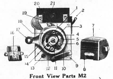
1. Condenser stud (short)
2. Primary lead assembly 3. Cam 4. Contact screw bracket assembly 5. Contact screw bracket fastening screw and washer 6. Primary lead fastening screw 7. High tension winding 8. Safety gap holder 9. Front plate 10. Cam screw 11. Breaker bar spring with nut and screw 12. Condenser stud (long) 13. Front plate fastening screw and washer 14. Cam screw washer 15. Breaker bar with platinum point 16. Condenser 17. Advance lever 18. Breaker bar bearing screw 19. Contact screw with platinum point 20. Contact screw lock nut 21. Secondary distributor carbon brush |
|
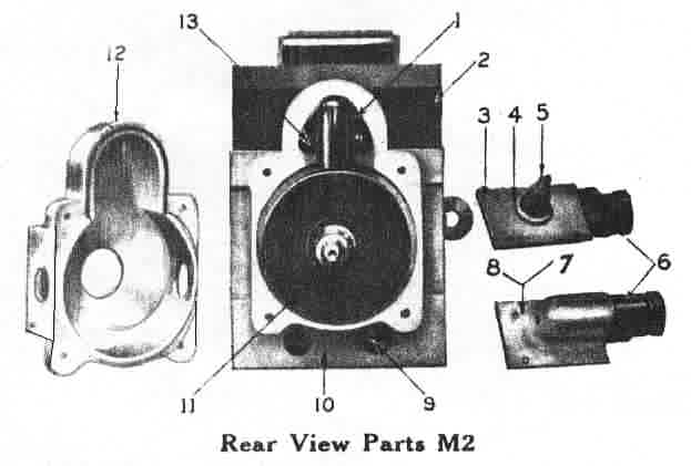
1. Secondary distributor brush
holder
2. Gap protector 3. Brush holder gasket 4. Brush holder ring gasket 5. Brush and spring assembly 6. Collector brush holder 7. Brush holder support (R.H.) 8. Brush holder support (L.H.) 9. Back plate fastening screw 10. Back plate 11. Secondary spool 12. Back plate cap with gasket 13. Secondary distributor brush holder screw and washer |
|
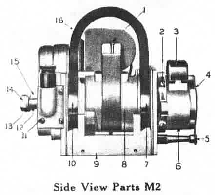
1. High tension winding screw
and washers
2. Advance lever fastening screw and washer 3. Breaker box cover 4. Condenser cover 5. Spring assembly for condenser cover 6. Breaker assembly 7. Bearing holder (Breaker end) 8. Pole structure 9. Base 10. Bearing holder (drive end) 11. Brush holder support fastening screw and washer 12. Drive shaft 13. Shaft nut washer 14. Shaft nut 15. Drive key 16. Magnet |
Facilities for oiling are provided by an oil hole in the
side of the instrument, and ten drops of light oil every hundred miles
are sufficient. Before oiling it is advisable to clean the oil hole from
dust and grit. The breaker lever bearing should be lubricated with a few
drops of light oil applied with, for example, a tooth pick, every 500 miles.
The proper distance between the platinum contact points
when separated should be .020" or 0.5mm. If the platinum contacts flash
badly there is a possibility that there is oil on the points or perhaps
the condenser is not making good contact. Examine the screws holding the
condenser and see that they are tight.
Magneto cut-out become accidently shorted or grounded; this will cause the motor to go dead or prevent starting. If this is suspected, disconnect the cut-out cable from the magneto.
For a single cylinder motor fitted with the DIXIE M1 magneto, rotate the crank shaft so as to bring the piston to the upper dead centre of the compression stroke. With the timing lever fully retarded, the platinum points of the circuit breaker should be about to separate.
For motors of the twin cylinder type, equipped with the DIXIE M2 magneto, rotate the crank shaft so as to bring the piston of No. 1 cylinder, which is usually the rear one (the first in the direction of rotation) to the upper dead centre of the compression stroke, With the timing lever in the full retard position, the platinum points of the circuit breaker should be about to separate, when the fibre bumper of the breaker bar begins to ride on the nose of the cam marked No. 1.
Because the DIXIE magnetos are not particularly liked they are (still) less expensive than, for example, the Bosch ZEV and, as will be clear from the above explanations, can be very reliable too when correctly taken care of. The DIXIE is also easier and less expensive to restore. A further advantage of the DIXIE is its relatively easy conversion to other V-twin angles or direction of rotation because this all depends on the position of the cam (and the spool) on the magneto shaft. Furthermore, although spare parts like cams are rare it is also relatively easy to change the 42°, 45° and 50° cams (corresponding to the angle between the cylinders) to any of the other values simply by grinding one of the cams until the wanted ignition timing is achieved by checking it on the engine in the manner as explained above. Of course the grinding should be done very carefully and preferably by hand with a small stone.
It will be clear from the following explanations that
the 42°, 45° and 50° cams do not allow the maximum spark intensity
to occur at both cylinders. Because the Harley Davidson F model
cylinders are 45° apart, when cylinder 1 fires the crank pin
will travel one revolution to come to cylinder 1 again, then 45 more to
cylinder 2 or 360° and 45° thus 405° in all, before No.2 fires.
No.1 will fire again, 360° minus 45° , or after 315°. The armature
travels at half the speed of the engine crank shaft and makes a spark every
half-revolution. Therefore the armature with its interruptor and collector
ring would travel 202.5° when the crank travels 405° after No.1
cylinder fires. When No.2 fires the crank pin on the engine will travel
315° before No.1 would fire again, and the magneto armature would travel
157.5°. Thus we have unequal distribution of the timing (202.5°
and 157.5°) which means that the distance A (Fig. 4) cannot be set
optimally for both cylinders (180° and 180° would be optimal).
However, the differences between 42°, 45° and
50° cams are so small that normally no problems with spark intensity
are encountered. The purist may however determine accurately, by using
an oscilloscope and different cam positions on the drive shaft, which position
gives the best spark intensity compromise for both cylinders.
(Part of the text and Figures in points II to VII have
been taken from the printed circular of the DIXIE)
Copyright PRAVG