[ Español ]
When I first started doing repairs of electronic devices I realized dry electrolytic capacitors were a common cause of failures. Their measured capacity is almost correct but their internal resistance rises causing many problems. This is common in capacitors running hot for example in switching power supplies.
I shopped around to buy an ESR meter but nobody knew what I was talking about, so I decided to build one from common components. A friend pointed me to this site and told me it worked fine:
http://www.albany.net/~gwoods/esr_meter/esr_meter_index.html
(Courtesy of Gary Woods)
And it did! Once calibrated it works great. To calibrate it requires nothing special,
just connect some resistors of known value and adjust some presets to have the meter
show the right value at various scale points.
My surprise however was some time ago when I found out Gary Woods page no longer existed. So far I could not find another web with its schematic and instructions so I have put them here:
Important notes:
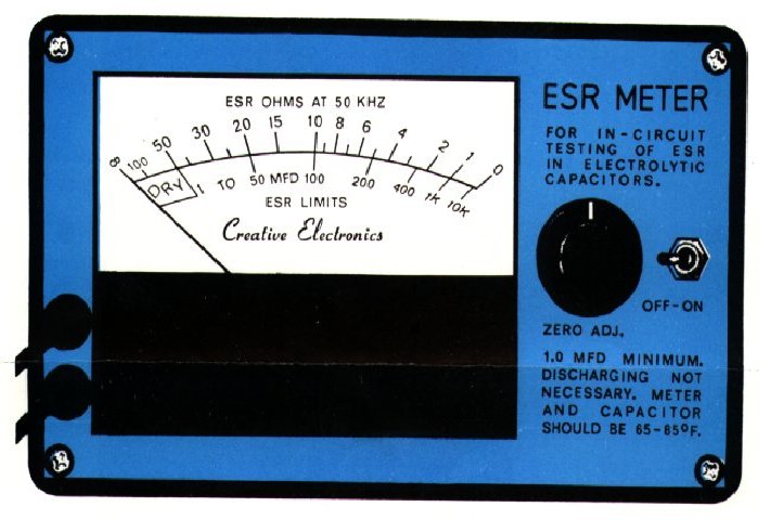
1N34A are germanium diodes, normal silicon diodes will not work. The meter is a 1mA needle ammeter.
This is the scale to replace the ammeter scale:
And this is the explanation that came with these pictures:
esrsch.txt