Upon Team scR’s receipt of new rear wheel bearings from a sponsor, it was noted that there was a significant increase in play in the bearings. One of these bearings was sent for design analysis, along with a pair of stock bearings removed after one race weekend. As a result of some on-track testing, a failure analysis of a new bearing was also completed.
Perform design comparison between old bearings removed from #34 and compare to the new bearings with increased play. Also, perform failure analysis on removed bearing and bearing that failed on track.
- RESULTS
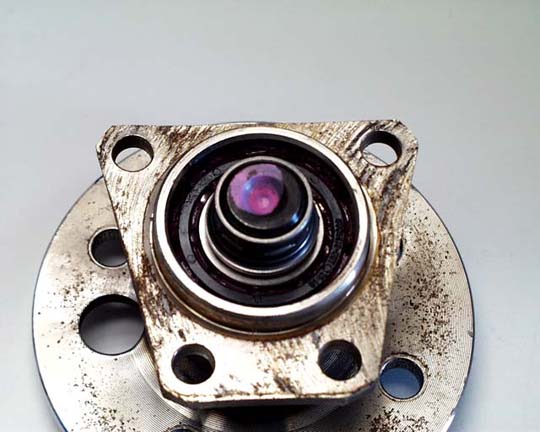
Stock Design:
These bearings were removed from the #34 car after one complete race weekend. There was very little evidence of bearing failure based on the feel of the bearing motion (both in endplay and in rotation). Only one sample was disassembled for analysis.
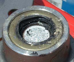
Removal of the endcap showed a ring that was pressed onto the spindle shaft and crimped into a recess on the spindle (Figure 1, Page 6). A grinder was used to remove a section of this ring and the remaining portion was pried off. Beneath this ring were two collars that were pressed into another recess on the spindle. These were removed using a screwdriver and a small hammer. The spindle was then pressed out, taking care not to damage the bearing races and retainers. All parts were then cleaned with soap and water to remove the grease, washed with acetone, and sprayed with a light mist of WD-40 to prevent rusting.
The design of the bearing used two ball bearings with races designed to handle light to moderate thrust loads, similar to a double row angular contact ball bearing. The design was such that one of the bearings absorbed the "push" load, whereas the other absorbed the "pull" load. The bearing retainers were made from an engineered polymeric material, which was not analyzed. The bearing races were contoured to maximize the contact area between the ball and the raceway.
Analysis of the spindle revealed the shaft diameter to be 0.910 in. The shaft material was AISI 1070 and was case hardened to 78 Ra, with a core hardness of 66 Ra. The part appeared to be cast into rough shape with final machining done on the wheel flange, seal area, and bearing contact areas. Additional grooves and tapers were also machined for the retention devices.
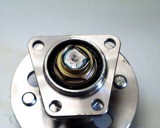
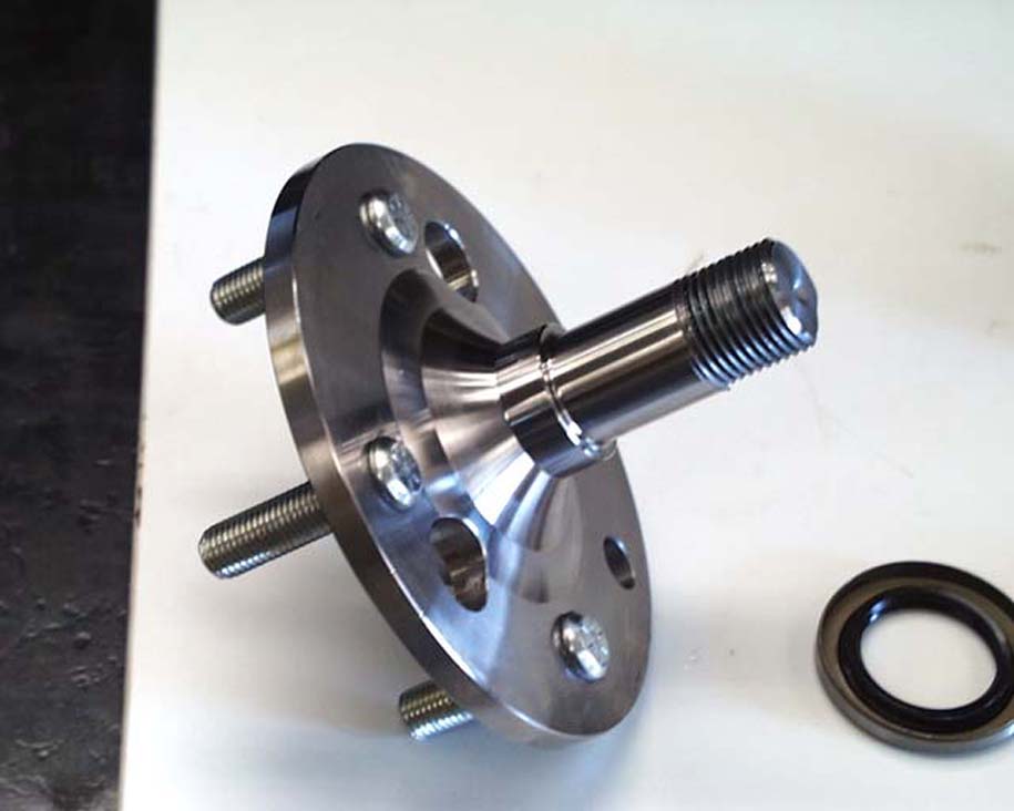
New Design:
This bearing was to be used on the #34 car as a replacement for the stock units. However, because the endplay seemed too large, the bearing was sent for design analysis and comparison to the stock design.
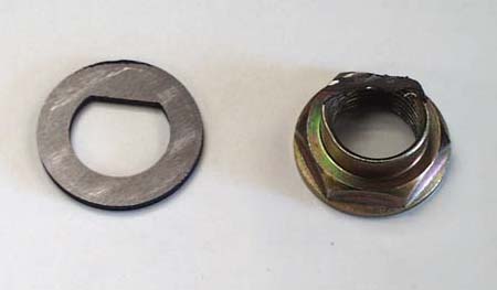
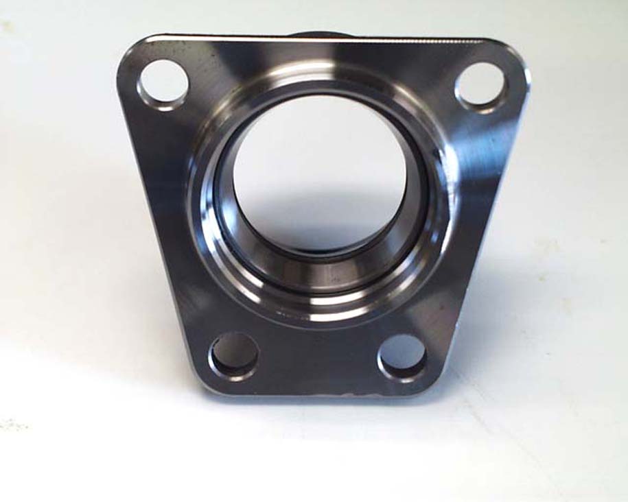
Removal of the endcap showed a nut that had been threaded onto the end of the spindle shaft (Figure 2, Page 6). The spindle had a machined flat approximately ¾ in wide, and the nut was crushed into this flat to prevent rotation. A grinder was used to remove the crushed portion, and the remainder of the nut was un-screwed. The spindle was then pressed out of the assembly, taking care not to damage the bearing races and retainers. The outboard bearing was then pressed off the spindle shaft. The outer races were removed from the wheel bearing housing using a brass rod and arbor press. All parts were then cleaned with soap and water to remove the grease, washed with acetone, and sprayed with a light mist of WD-40 to prevent rusting.
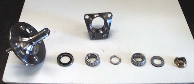
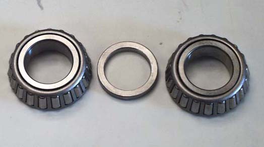
The design of the bearing used a double tapered roller to handle both radial and large thrust loads simultaneously. The bearings were a standard size bearing and were identified with "Koyo USA HI-CAP L44643 R" (cones) and "Koyo USA HI-CAP L44610" (cups). A spacer between the cones fixed the bearing spacing (Figure 6, Page 8).
Analysis of the spindle revealed the shaft diameter to be 1.000 in. The shaft material was AISI 1040/1045 (testing showed the carbon level to be 0.425%, which is between these standards) and had a hardness of 51 Ra. The part appeared to be cast into near final shape, with final machining done on the whole part except for the cup in the center of the wheel mount flange. The spindle end was machined for a 1"-12 threaded nut.
Failure Analyses:
Stock Design:
The bearings submitted for analysis were run for one full weekend of racing, which included practice, qualifying, and racing. Upon initial examination, there was little to no evidence of bearing failure, as there was no detectable endplay and no noise or out of the ordinary feel in bearing rotation. The same sample used for design analysis was used for the failure analysis.
Preliminary examination of the bearing after disassembly revealed that the balls for the outboard bearing (bearing closest to wheel) had blued due to heat. The grease did not show any signs of breakdown and contained very little dirt. The bearing raceways did not appear to contain any defects. However, upon microscopic examination, a small degree of pitting was found on the outer race of the outboard bearing, indicating that the bearing was beginning to fail. There were no indications that the spindle was beginning to fail.
New Design:
Parts using the new bearing design have never been run using the #34 car. However, another member of the SPC installed the bearings on his mostly stock car. The failure described below is from his vehicle at Blackhawk Farms raceway in Rockton, Illinois.
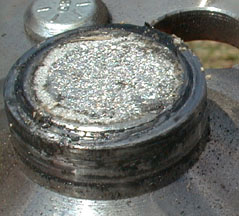
Examination of the bearing after failure showed that the part had fractured just beyond the fillet of the step of the spindle to the 1.000 in size. This location also corresponded to the point at which the outboard bearing was pressed to. The fracture seemed to initiate in fatigue with a circumferential crack that grew to about 1/8 in deep (700 miles is equivalent to 583,000 cycles with a stock size tire) (Figure 8, Page 9). At this point, the part appeared to fracture due to an overload condition. However, it is not possible to say for certain what happened without the actual parts in hand.
After discussions with a metallurgist of 30+ years, it was discovered that parts of this manufacturing process typically undergo a hardening process to increase toughness and strength. Because the part was cast and at a relatively low hardness level, it was weak and very brittle.
- DISPOSITION OF TEST ARTICLES