cathode ray
oscilloscope (CRO) The
cathode ray oscilloscope is an electronic instrument used
mainly for (i) studying the waveform of
an ac signal, sound or even heartbeats,
(ii) measurements of ac voltages, and (iii) comparison of frequencies
of two ac signals.
It consists of a cathode
ray tube and associated electronic circuits. The ac voltage
is applied to the Y plates of the cathode ray tube* . The spot on
the screen will trace out a vertical line proportional to the applied voltage.
In order to convert this into a waveform, a sweep voltage is
applied into the X plates, by a circuit called time base. When
sweep cycle is synchronized to the signal
frequency, the image is repeated on the
screen and appears stationary (see fig. c3).

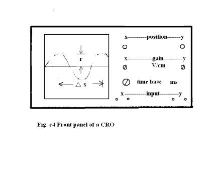
To find the
frequency of ac voltage measure the distance between the
peaks, D x (see fig.c4). Note the setting of the time base control
(t ms/cm). Time between peaks (T) is the product of D x and t. Reciprocal
of T gives the frequency of ac voltage.
Measure the
amplitude of the waveform (that is. center line to the peak)
on the screen (y cm). Also note the setting of the vertical
gain control ( m V/cm). The peak voltage is m ´
y volts.
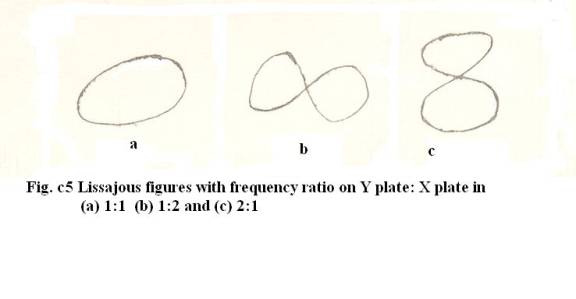
If two ac
signals are fed simultaneously, one into the X plates of unknown
frequency and the other into the Y plates (from an oscillator),
Lissajous pattern appears on the screen that depend on
the ratio of two frequencies (fig. c5). By varying the frequency
of the oscillator, we can get desired shape and find the
unknown frequency.