|
HOME
|
| I | INTRODUCTION |
Optics, branch of physical science
dealing with the propagation and behavior of light. In a general sense, light is
that part of the electromagnetic spectrum that extends from X rays to microwaves
and includes the radiant energy that produces the sensation of vision (see
Electromagnetic Radiation). The study of optics is
divided into geometrical optics and physical optics, and these branches are
discussed below.![]()

| II | NATURE OF LIGHT |
Radiant energy has a dual nature and obeys laws that may be explained in terms of a stream of particles, or packets of energy, called photons, or in terms of a train of transverse waves (see Photon; Radiation; Wave Motion). The concept of photons is used to explain the interactions of light and matter that result in a change in the form of energy, as in the case of the photoelectric cell or luminescence. The concept of transverse waves is usually used to explain the propagation of light through various substances and some of the phenomena of image formation. Geometrically, a simple transverse wave may be described by points that oscillate in the same plane back and forth across an axis perpendicular to the direction of oscillation such that at any instant of time the envelope of these points is, for example, a sine function that intersects the axis (see Geometry; Trigonometry). The wave front progresses, and the radiant energy travels along the axis. The oscillating point may be considered to describe the vibration of the electric component, or vector, of the light wave. The magnetic component vibrates in a direction perpendicular to that of the electric vector and to the axis. The magnetic component is ineffective and may be ignored in the study of visible light. The number of complete oscillations, or vibrations (see Oscillation), per second of a point on the light wave is known as the frequency. The wavelength is the linear distance parallel to the axis between two points in the same phase, or occupying equivalent positions on the wave, for example, the distance from maximum to maximum in the case of a sine function representation. Differences in wavelength manifest themselves as differences in color in the visible spectrum. The visible range extends from about 350 nanometers (violet) to 750 nanometers (red), a nanometer being equal to a billionth of a meter, or 4 × 10⁻⁸ in. White light is a mixture of the visible wavelengths. No sharp boundaries exist between wavelength regions, but 10 nanometers may be taken as the low wavelength limit for ultraviolet radiation. Infrared radiation, which includes heat energy, includes the wavelengths from about 700 nanometers to approximately 1 mm. The velocity of an electromagnetic wave is the product of the frequency and the wavelength. In a vacuum this velocity is the same for all wavelengths. The velocity of light in material substances is, with few exceptions, less than in a vacuum. Also, in material substances this velocity is different for different wavelengths, as a result of dispersion. The ratio of the velocity of light in vacuum to the velocity of a particular wavelength of light in a substance is known as the index of refraction of that substance for the given wavelength. The index of refraction of a vacuum is equal to 1; that of air is 1.00029, but for most applications it is also taken to be 1.
The laws of reflection and refraction of light are usually derived
using the wave theory of light introduced by the Dutch mathematician,
astronomer, and physical scientist Christiaan Huygens. Huygens's principle
states that every point on an initial wave front may be considered as the source
of small, secondary spherical wavelets that spread out in all directions from
their centers with the same velocity, frequency, and wavelength as the parent
wave front. When the wavelets encounter another medium or object, each point on
the boundary becomes a source of two new sets of waves. The reflected set
travels back into the first medium, and the refracted set enters the second
medium. It is sometimes simpler and sufficient to represent the propagation of
light by rays rather than by waves. The ray is the flow line, or direction of
travel, of radiant energy, and the assumption is made that light does not bend
around corners. In geometrical optics the wave theory of light is ignored and
rays are traced through an optical system by applying the laws of reflection and
refraction.![]()
| III | GEOMETRICAL OPTICS |
This area of optical science concerns the application of laws of
reflection and refraction of light in the design of lenses (see Lenses below)
and other optical components of instruments. If a light ray that is traveling
through one homogeneous medium is incident on the surface of a second
homogeneous medium, part of the light is reflected and part may enter the second
medium as the refracted ray and may or may not undergo absorption in the second
medium.![]()
| A | Reflection and Refraction |
The amount of light reflected depends on the ratio of the refractive
indexes for the two media. The plane of incidence contains the incident ray and
the normal (line perpendicular) to the surface at the point of incidence (see
Fig. 1). The angle of incidence (reflection or refraction) is the angle between
the incident (reflected or refracted) ray and this normal. The laws of
reflection state that the angle of incidence is equal to the angle of reflection
and that the incident ray, the reflected ray, and the normal to the surface at
the point of incidence all lie in the same plane. If the surface of the second
medium is smooth or polished, it may act as a mirror and produce a reflected
image. If the mirror is flat, or plane, the image of the object appears to lie
behind the mirror at a distance equal to the distance between the object and the
surface of the mirror. The light source in Fig. 2 is the object A, and a point
on A sends out rays in all directions. The two rays that strike the mirror at B
and C, for example, are reflected as the rays BD and CE. To an observer in front
of the mirror, these rays appear to come from the point F behind the mirror. It
follows from the laws of reflection that CF and BF form the same angle with the
surface of the mirror as do AC and AB. If the surface of the second medium is
rough, then normals to various points of the surface lie in random directions.
In that case, rays that may lie in the same plane when they emerge from a point
source nevertheless lie in random planes of incidence, and therefore of
reflection, and are scattered and cannot form an image.
 |
 |
Not all of the light that strikes a mirror is reflected; some of the light
can pass through the mirror or be absorbed by the mirror. Many scientists
thought a perfect mirror—one that reflects 100 percent of the light that strikes
it—could not exist. However, in 1998, scientists made a perfect mirror by
stacking up microscopic layers of tellurium and the plastic polystyrene.![]()
| A1 | Snell's Law |
This important law, named after the Dutch mathematician Willebrord Snell, states that the product of the refractive index and the sine of the angle of incidence of a ray in one medium is equal to the product of the refractive index and the sine of the angle of refraction in a successive medium. Also, the incident ray, the refracted ray, and the normal to the boundary at the point of incidence all lie in the same plane. Generally, the refractive index of a denser transparent substance is higher than that of a less dense material; that is, the velocity of light is lower in the denser substance. If a ray is incident obliquely, then a ray entering a medium with a higher refractive index is bent toward the normal, and a ray entering a medium of lower refractive index is deviated away from the normal. Rays incident along the normal are reflected and refracted along the normal. In making calculations, the optical path, which is defined as the product of the distance a ray travels in a given medium and the refractive index of that medium, is the important consideration. To an observer in a less dense medium such as air, an object in a denser medium appears to lie closer to the boundary than is the actual case. A common example, that of an object lying underwater observed from above water, is shown in Fig. 3. Oblique rays are chosen only for ease of illustration. The ray DB from the object at D is bent away from the normal to A. The object, therefore, appears to lie at C, where the line ABC intersects a line normal to the surface of the water and passing through D.
The path of light passing through several media with parallel
boundaries is shown in Fig. 4. The refractive index of water is lower than that
of glass. Because the refractive index of the first and last medium is the same,
the ray emerges parallel to the incident ray AB, but it is displaced.
 |
 |
![]()
| A2 | Prism |
If light passes through a prism, a transparent object with flat,
polished surfaces at angles to one another, the exit ray is no longer parallel
to the incident ray. Because the refractive index of a substance varies for the
different wavelengths, a prism can spread out the various wavelengths of light
contained in an incident beam and form a spectrum. In Fig. 5, the angle CBD
between the path of the incident ray and the path of the emergent ray is the
angle of deviation. If the angle the incident ray makes with the normal is equal
to the angle made by the emergent ray, the deviation is at a minimum. The
refractive index of the prism can be calculated by measuring the angle of
minimum deviation and the angle between the faces of the prism.
|
| A3 | Critical Angle |
 Given that a ray is bent
away from the normal when it enters a less dense medium and that the deviation
from the normal increases as the angle of incidence increases, an angle of incidence
exists, known as the critical angle, such that the refracted ray makes an angle
of 90° with the normal to the surface and travels along the boundary between
the two media. If the angle of incidence is increased beyond the critical angle,
the light rays will be totally reflected back into the incident medium. Total
reflection cannot occur if light is traveling from a less dense medium to a
denser one. The three drawings in Fig. 6 show ordinary refraction, refraction
at the critical angle, and total reflection. In the late 20th century,
a new, practical application of total reflection was found in the use of fiber
optics. If light enters a solid glass or plastic tube obliquely, the light can
be totally reflected at the boundary of the tube and, after a number of successive
total reflections, emerge from the other end. Glass fibers can be drawn to a
very small diameter, coated with a material of lower refractive index, and then
assembled into flexible bundles or fused into plates of fibers used to transmit
images. The flexible bundles, which can be used to provide illumination as well
as to transmit images, are valuable in medical examination, as they can be inserted
into various openings.
Given that a ray is bent
away from the normal when it enters a less dense medium and that the deviation
from the normal increases as the angle of incidence increases, an angle of incidence
exists, known as the critical angle, such that the refracted ray makes an angle
of 90° with the normal to the surface and travels along the boundary between
the two media. If the angle of incidence is increased beyond the critical angle,
the light rays will be totally reflected back into the incident medium. Total
reflection cannot occur if light is traveling from a less dense medium to a
denser one. The three drawings in Fig. 6 show ordinary refraction, refraction
at the critical angle, and total reflection. In the late 20th century,
a new, practical application of total reflection was found in the use of fiber
optics. If light enters a solid glass or plastic tube obliquely, the light can
be totally reflected at the boundary of the tube and, after a number of successive
total reflections, emerge from the other end. Glass fibers can be drawn to a
very small diameter, coated with a material of lower refractive index, and then
assembled into flexible bundles or fused into plates of fibers used to transmit
images. The flexible bundles, which can be used to provide illumination as well
as to transmit images, are valuable in medical examination, as they can be inserted
into various openings.
![]()
| B | Spherical and Aspherical Surfaces |
Traditionally, most of the terminology of geometrical optics was developed with reference to spherical reflecting and refracting surfaces. Aspherical surfaces, however, are sometimes involved. The optic axis is a reference line that is an axis of symmetry. If the optical component is spherical, the optic axis passes through the center of a lens or mirror and through the center of curvature. Light rays from a very distant source are considered to travel parallel to one another. If rays parallel to the optic axis are incident on a spherical surface, they are reflected or refracted so that they intersect or appear to intersect at a point on the optic axis. The distance between this point and the vertex of a mirror or a thin lens is the focal length. If a lens is thick, calculations are made with reference to planes called principal planes, rather than to the surface of the lens. A lens may have two focal lengths, depending on which surface (if the surfaces are not alike) the light strikes first. If an object is at the focal point, the rays emerging from it are made parallel to the optic axis after reflection or refraction. If rays from an object are converged by a lens or mirror so that they actually intersect in front of a mirror or behind a lens, the image is real and inverted, or upside down. If the rays diverge after reflection or refraction so that the light only appears to converge, the image is virtual and erect. The ratio of the height of the image to the height of the object is the lateral magnification.If it is understood that distances measured from the surface of a lens or mirror in the direction in which light is traveling are positive and distances measured in the opposite direction are negative, then if u is the object distance, v the image distance, and f is the focal length of a mirror or of a thin lens, the equation
| 1/v + 1/u = 1/f |
applies to spherical mirrors, and the equation
| 1/v - 1/u = 1/f |
applies to spherical lenses. If a simple lens has surfaces with radii r1 and r2, and the ratio of its refractive index to that of the medium surrounding it is n, then
| 1/f = (n - 1) (1/r1 - 1/r2) |
The focal length of a spherical mirror is equal
to half the radius of curvature. As is shown in Fig. 7, rays parallel to the
optic axis that are incident on a concave mirror with its center of curvature
at C are reflected so that they intersect at B, halfway between A and C. If
the object distance is greater than the distance AC, then the image is real,
inverted, and diminished. If the object lies between the center of curvature
and the focal point, the image is real, inverted, and enlarged. If the object
is located between the surface of the mirror and the focus, the image is virtual,
upright, and enlarged. Convex mirrors form only virtual, erect, and diminished
images.
|
|
| C | Lenses |
Lenses made with surfaces of small radii have the shorter focal lengths. A lens with two convex surfaces will always refract rays parallel to the optic axis so that they converge to a focus on the side of the lens opposite to the object. A concave lens surface will deviate incident rays parallel to the axis away from the axis, so that even if the second surface of the lens is convex, the rays diverge and only appear to come to a focus on the same side of the lens as the object. Concave lenses form only virtual, erect, and diminished images. If the object distance is greater than the focal length, a converging lens forms a real and inverted image. If the object is sufficiently far away, the image is smaller than the object. If the object distance is smaller than the focal length of this lens, the image is virtual, erect, and larger than the object. The observer is then using the lens as a magnifier or simple microscope. The angle subtended at the eye by this virtual enlarged image is greater than would be the angle subtended by the object if it were at the normal viewing distance. The ratio of these two angles is the magnifying power of the lens. A lens with a shorter focal length would cause the angle subtended by the virtual image to increase and thus cause the magnifying power to increase. The magnifying power of an instrument is a measure of its ability to bring the object apparently closer to the eye. This is distinct from the lateral magnification of a camera (see Photography) or telescope, for example, where the ratio of the actual dimensions of a real image to those of the object increases as the focal length increases. See Lens.
The amount of light a lens can admit increases with its diameter.
Because the area occupied by an image is proportional to the square of the focal
length of the lens, the light intensity over the image area is directly
proportional to the diameter of the lens and inversely proportional to the
square of the focal length. The image produced by a lens of 1-in. diameter and
8-in. focal length would be one-fourth as bright as the image formed by a lens
of 1-in. diameter and 4-in. focal length. The ratio of the focal length to the
effective diameter of a lens is its focal ratio or the so-called f-number.
The reciprocal of this ratio is called the relative aperture. Lenses having the
same relative aperture have the same light-gathering power, regardless of the
actual diameters and focal lengths.![]()
| D | Aberration |
Geometrical optics predicts that rays of light emanating from a point are imaged by spherical optical elements as a small blur. The outer parts of a spherical surface have a different focal length than does the central area, and this defect would cause a point to be imaged as a small circle. The difference in focal length for the various parts of the spherical section is called spherical aberration. If, instead of being a portion of a sphere, a concave mirror is a section of a paraboloid (see Parabola) of revolution, parallel rays incident on all areas of the surface are reflected to a point without spherical aberration. Combinations of convex and concave lenses can help to correct spherical aberration, but this defect cannot be eliminated from a single spherical lens for a real object and image.
The manifestation of differences in lateral magnification for rays
coming from an object point not on the optic axis is called coma. If coma is
present, light from a point is spread out into a family of circles that fit into
a cone, and in a plane perpendicular to the optic axis, the image pattern is
comet shaped. Coma may be eliminated for a single object-image point pair, but
not for all such points, by a suitable choice of surfaces. Corresponding or
conjugate object and image points, free from both spherical aberration and coma,
are known as aplanatic points, and a lens having such a pair of points is called
an aplanatic lens. Astigmatism is the defect in which the light coming from an
off-axis object point is spread along the direction of the optic axis. If the
object is a vertical line, the cross section of the refracted beam is an ellipse
that collapses first into a horizontal line, spreads out again, and later
becomes a vertical line. If a flat object has any extent, the surface of best
focus is curved, or curvature of field results. Distortion arises from a
variation of magnification with axial distance and is not caused by a lack of
sharpness in the image. Because the index of refraction varies with wavelength,
the focal length of a lens also varies and causes longitudinal or axial
chromatic aberration. Magnification of different image sizes by various
wavelengths is known as lateral chromatic aberration. Converging and diverging
lenses grouped together, and combinations of glasses with different dispersions,
help to minimize chromatic aberration. Mirrors are free of this defect. In
general, achromatic lens combinations are corrected for chromatic aberration for
two or three colors.![]()
| IV | PHYSICAL OPTICS |
This branch of optical science concerns the study of the polarization of light, interference and diffraction, and the spectral emission, composition, and absorption of light.
| A | Polarization of Light |
The atoms in an ordinary light source emit pulses of radiation of extremely short duration. Each pulse from a single atom is a nearly monochromatic (consisting of a single wavelength) wave train. The electric vector corresponding to the wave does not rotate about the axis across which it oscillates as the wave travels through space, but keeps the same angle, or azimuth, with respect to the direction of travel. The initial azimuth can have any value. When a large number of atoms are emitting light, these azimuths are randomly distributed, the properties of the light beam are the same in all directions, and the light is said to be unpolarized. If the electric vectors for each wave all have the same azimuth angle (or all the transverse waves lie in the same plane), the light is plane, or linearly, polarized. The equations that describe the behavior of electromagnetic waves involve two sets of waves, one with the electric vector vibrating perpendicular to the plane of incidence and the other with the electric vector vibrating parallel to the plane of incidence, and all light can be considered as having a component of its electric vector vibrating in each of these planes. A certain synchronism of phase difference may persist in time between the two vibrations of the component, or the phase differences may be random. If light is linearly polarized, for example, this phase difference becomes zero or 180°. If the phase relationship is random, but more of one component is present, the light is partially polarized. When light is scattered by dust particles, for instance, the light scattered 90° to the original path of the beam is plane polarized, explaining why skylight from the zenith is markedly polarized. At angles other than zero or 90° of incidence, the reflectance at the boundary between two media is not the same for those two components of vibrations. Less of the component that vibrates parallel to the plane of incidence is reflected. If light is incident on a nonabsorbing medium at the so-called Brewster's angle, named after the British physicist David Brewster, the reflectance of the component vibrating parallel to the plane of incidence is zero. At this angle of incidence, the reflected ray would be perpendicular to the refracted ray, and the tangent of this angle of incidence is equal to the refractive index of the second medium if the first medium is air.
Certain substances are anisotropic, or display properties with different values when measured along axes in different directions, and the velocity of light in them depends on the direction in which the light is traveling. Some crystals are birefringent, or exhibit double refraction (see Crystal). Unless light is traveling parallel to an axis of symmetry with respect to the structure of the crystals (the optic axis of the crystal), it is separated into two parts that travel with different velocities. A uniaxial crystal has one axis. The component with the electric vector vibrating in a plane containing the optic axis is the ordinary ray; its velocity is the same in all directions through the crystal, and Snell's law of refraction holds. The component vibrating perpendicular to the plane of the optic axis forms the extraordinary ray, and the velocity of this ray depends on its direction through the crystal. If the ordinary ray travels faster than the extraordinary ray, the birefringence is positive; otherwise the birefringence is negative.
If a crystal is biaxial, no component exists for which the velocity is independent of the direction of travel. Birefringent materials can be cut and shaped to introduce specific phase differences between two sets of polarized waves, to separate them, or to analyze the state of polarization of any incident light. A polarizer transmits only one component of vibration either by reflecting away the other by means of properly cut prism combinations or by absorbing the second component. A material that preferentially absorbs one component of vibration exhibits dichroism, and Polaroid is an example of this. Polaroid consists of many small dichroic crystals embedded in plastic and identically oriented. If light is unpolarized, Polaroid absorbs approximately half of it. Because light reflected from a large flat surface such as water or a wet road is partially polarized, properly oriented Polaroid can absorb more than half of this reflected glare light. This explains the effectiveness of Polaroid sunglasses. The so-called analyzer may be physically the same as a polarizer. If a polarizer and analyzer are crossed, the analyzer is oriented to allow transmission of vibrations lying in a plane perpendicular to those transmitted by the polarizer, and blocks or extinguishes the light passed by the polarizer. Substances that are optically active rotate the plane of linearly polarized light. Either a crystal or a solution of sugar, for example, may be optically active. If a solution of sugar is placed between a crossed polarizer and analyzer, the light is able to pass through. The amount of rotation of the analyzer required to restore extinction of the light determines the concentration of the solution. The polarimeter is based on this principle.
Some substances, such as glass and plastic, that are not normally doubly refracting, may become so if subjected to stress. If such stressed materials are placed between a polarizer and analyzer, the bright and dark areas that are seen give information about the strains. The technology of photoelasticity is based on double refraction produced by stresses.
Birefringence can also be introduced in otherwise homogeneous
materials by magnetic and electric fields. The Faraday effect, named after the
British physicist and chemist Michael Faraday, refers to the fact that a strong
magnetic field across a liquid may cause it to become doubly refracting, a
phenomenon known as the Kerr effect, after the British physicist John Kerr. If
an appropriate material is placed between a crossed polarizer and analyzer,
light is transmitted depending on whether the electric field is on or off. This
can act as a very rapid light switch or modulator.![]()
| B | Interference and Diffraction |
When two light beams cross, they may interfere or interact in such a way that the resultant intensity pattern is affected (see Interference). The degree of coherence, or waves in phase and of one wavelength, is related to the ability of waves to produce a steady state that depends on the phase relationships of successive wave fronts remaining constant with time. If the phase relationship changes rapidly and randomly, two beams are incoherent. If two wave trains are coherent and if the maximum of one wave coincides with the maximum of another, the two waves combine to produce a greater intensity in that place than if the two beams were present but not coherent. If coherence exists and the maximum of one wave coincides with the minimum of another wave, the two waves will cancel each other in part or completely, thus decreasing the intensity. A dark and bright pattern consisting of interference fringes may be formed. To produce a steady interference pattern the two wave trains must be polarized in the same plane. Atoms in an ordinary light source radiate independently, so a large light source usually emits incoherent radiation. To obtain coherent light from such a source, a small portion of the light is selected by means of a pinhole or slit. If this portion is then again split by double slits, double mirrors, or double prisms, and the two parts made to travel definite but different paths before they are combined again, an interference pattern results. Devices that do this are called interferometers; they are used in measuring such things as diameters of stars, distances or thicknesses, and deviations of an optical surface from the required shape in terms of wavelengths of light (see Interferometer). Such an interference pattern was first demonstrated by the British physicist Thomas Young in the experiment illustrated in Fig. 8. Light that had passed through one pinhole illuminated an opaque surface that contained two pinholes. The light that passed through the two pinholes formed a pattern of alternately bright and dark circular fringes on a screen. Wavelets are drawn in the illustration to show that at points such as A, C, and E (intersection of solid line with solid line) the waves from the two pinholes arrive in phase and combine to increase the intensity. At other points, such as B and D (intersection of solid line with dashed line), the waves are 180° out of phase and cancel each other.
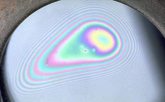
Light reflected at each surface of an extremely thin transparent film on a smooth surface can interfere. The rainbow colors of a film of oil on water are a result of interference, and they demonstrate the importance of the ratio of film thickness to wavelength. A single film or several films of different material can be used to increase or decrease the reflectance of a surface. Dichroic beam splitters are stacks of films of more than one material, controlled in thickness so that one band of wavelengths is reflected and another band of wavelengths is transmitted. An interference filter made of such films transmits an extremely narrow band of wavelengths and reflects the remainder. The shape of the surface of an optical element can be checked by touching it to a master lens, or flat, and observing the fringe pattern formed because of the thin layer of air remaining between the two surfaces.
Light incident on the edge of an obstacle is bent or diffracted, and the obstacle does not form a sharp geometric shadow. The points on the edge of the obstacle act as a source of coherent waves, and interference fringes, called a diffraction pattern, are formed. The shape of the edge of the obstacle is not exactly reproduced because part of the wave front is cut off. Because light passes through a finite aperture when it goes through a lens, a diffraction pattern is formed around the image of an object. If the object is extremely small, the diffraction pattern appears as a series of concentric bright and dark rings around a central disk called the Airy disk, after the British astronomer George Biddell Airy. This is true for an aberration-free lens. If two particles are so close together that the two diffraction patterns overlap and the bright rings of one pattern fall on the dark rings of the second pattern, the two particles appear to merge, or cannot be resolved. The German physicist and optician Ernst Karl Abbe first explained image formation by a microscope with a theory based on the interference of diffraction patterns of various points on the object.
Fourier analysis is a mathematical treatment, named after the French mathematician Jean Fourier, that assigns a frequency spectrum to an object and permits the calculation of the diffraction pattern of an object at some plane intermediate between the object plane and image plane, allowing the appearance of the image to be calculated. This is possible because a complex wave can be considered to consist of a combination of simple waves. Optical systems are sometimes evaluated by choosing an object of known Fourier components and then evaluating the Fourier components present in the image. Such procedures measure the optical transfer function. Extrapolations of these techniques sometimes allow extraction of information from poor images. Statistical theories have also been included in analyses of the recording of images.
A diffraction grating consists of several thousand slits that are
equal in width and equally spaced (formed by ruling lines on glass or metal with
a fine diamond point). Each slit gives rise to a diffraction pattern, and the
many diffraction patterns interfere. If white light is incident, a continuous
spectrum is formed. Prisms and gratings are used in instruments such as
monochromators, spectrographs, or spectrophotometers to provide nearly
monochromatic light or to analyze the wavelengths present in the incident light
(see Mass Spectrometer; Spectroheliograph).![]()
| C | Stimulated Emission |
The atoms in common light sources, such as the incandescent lamp, fluorescent lamp, and neon lamp, produce light by spontaneous emission, and the radiation is incoherent. If a sufficient number of atoms have absorbed energy so that they are excited into appropriate states of higher energy, stimulated emission can occur. Light of a certain wavelength can produce additional light of the same wavelength that has the same phase and direction as the original light, and it will be coherent. Stimulated emission amplifies the amount of radiation having a given wavelength, and this radiation has a very narrow beam spread and a long coherence path. The material that is excited may be a gas, a liquid, or solid, but it must be contained or shaped to form an interferometer in which the wavelength being amplified is reflected back and forth many times. A small fraction of the excited radiation is transmitted by one of the mirrors of the interferometers. Maser is an acronym for microwave amplification by stimulated emission of radiation (see Electronics). If optical frequencies are being amplified by stimulated emission, the term laser, an acronym for light amplification by stimulated emission of radiation, is commonly used. Energizing a large number of atoms to be in the appropriate upper state is called pumping. Pumping may be optical or electrical. Because lasers can be made to emit pulses of extremely high energy that have a very narrow beam spread, laser light sent to the moon and reflected back to the earth can be detected. The intense narrow beam of the laser has found practical application in surgery and in the cutting of metals.
The Hungarian-born British physicist and electrical engineer Dennis Gabor first noted that if the diffraction pattern of an object could be recorded and the phase information also retained, the image of the object could be reconstructed by coherent illumination of the recorded diffraction pattern. Illuminating the diffraction pattern with a wavelength longer than that used to produce the diffraction pattern would result in magnification. Because the absolute phase of a light wave cannot be directly detected physically, it was necessary to provide a reference beam coherent with the beam illuminating the object to interfere with the diffraction pattern and provide phase information. Before the development of the laser, the Gabor scheme was limited by the lack of sufficiently intense coherent light sources.
A hologram is a photographic record of the interference between a reference beam and the diffraction pattern of the object. Light from a single laser is separated into two beams. The reference beam illuminates the photographic plate, perhaps via a lens and mirror, and the second beam illuminates the object, which forms a diffraction pattern on the photographic plate. If the processed hologram is illuminated by coherent light, not necessarily of the same wavelength that was used to make the hologram, the image of the object is reconstructed, and a three-dimensional image of the object can be obtained. (see Holography).
Intense, coherent laser beams permit the study of optical effects that are produced by the interaction of certain substances with electric fields and that depend on the square or third power of the field strength. This area of study is called nonlinear optics, and the interactions being studied affect the refractive index of the substances. The Kerr effect, mentioned earlier, belongs to this group of phenomena.
Harmonic generation of light has been observed. Infrared laser light
of wavelength 1.06 micrometers, for example, can be changed to green light with
a wavelength of 0.53 micrometers in a crystal of barium sodium niobate. Broadly
tunable sources of coherent light in the visible and near-infrared ranges can be
produced by pumping with light or radiation of shorter wavelengths. A lithium
niobate crystal can be made to fluoresce in red, yellow, and green by pumping it
with laser light having a wavelength of 488 nanometers. Certain scattering
phenomena can be stimulated by a single laser to produce a source of intense,
pulsed, monochromatic beams at a wide variety of wavelengths. One of the
phenomena observed in high-power optical experiments is a self-focusing effect
that produces extremely short-lived filaments as small as 5 micrometers in
diameter. Nonlinear optical effects are applied in developing efficient
broadband modulators for communication systems.![]()