Laws
of Electrodynamics
Physics
World
Back to Electrodynamics
Historical Outline
of Electrodynamics
600
B.C. – Thales
of Miletus, a Greek mathematician, astronomer and philosopher, noted that when
amber is rubber with silk it produces sparks and can attract bits of straw, silk
or other light objects. It should be noted that the Greek word for amber is elektron.
This term will be used thousands of years later in creating new terminology such
as electron, electronics, electric, electricity,
electrodynamics, etc. Thales
also noted the attractive power of a natural magnetic rock called loadstone
found in a place called “Magnesia.” This word will also be used later to
refer to magnet, magnetism and other such terminology. [1]
1269
A.D. – Peter
Peregrinus of Maricourt
from Picardy using a
globular magnet or loadstone and let a needle set on the magnet and, when the
needle settled, drew a lines parallel to the needle. Eventually the entire globe
was covered with lines. The lines formed circles which crossed at two points on
opposite sides of the magnet which reminded him of the meridians on earth which
all passed through the north and south poles of the magnet. Struck by the
analogy Maricourt proposed to call these two points on the magnet the poles
of the magnet. [2]
1600
A.D. – William
Gilbert of England performed the first systematic experiments of electric
and magnetic phenomena. His results were described in is famous book De
Magnete. Gilbert also invented the electroscope for measuring electrostatic
effects. He was also the first person to realize that the earth itself is a huge
magnet as well as demonstrate that amber was not the only substance that
displayed electrification properties. Gilbert was the one who used the term electric
to refer to the forces that, e.g. a piece of amber rubbed with silk exerted on
bits of matter. Thus he originated the term electric force. [3]
1750
A.D. – Benjamin
Franklin of America experimented with electricity that led him to his
invention of the lightning rod. He is also credited for the law of conservation
of charge and also determined that there were both positive and negative
charges. [4][5]
1795
A.D. – Charles Augustine de Coulomb
of France measured electric and magnetic forces with a delicate torsion balance.
The results of these experiments resulted in what is now referred to as Coulomb’s
Law. [5]
1800
A.D. – Alessandro
Volta of Italy invented the voltaic cell and, connecting them in series,
created the first battery. [5]
1819
A.D. – Hans
Christian Oersted, during a lab demonstration, accidentally found that a
current carrying wire caused a nearby compass needle to deflect thus discovering
that electric current produces magnetism. [5]
1831
A.D. – Michael
Faraday of London showed that a time varying magnetic field produces an
electric current. Thus Faraday showed that magnetism could produce electricity.
[5]
1873
A.D. – James
Clerk Maxwell used Faraday’s investigations to enable him to establish the
interdependency of electricity and magnetism. In his classic treatise of 1872 he
published the first unified theory of electricity and magnetism and founded the
science of electromagnetics. Maxwell also postulated that light was an
electromagnetic wave. [5]
1888
A.D. – Heinrich
Hertz of Germany vindicated Maxwell’s theories by generating radio waves
of about 5 meters in wavelength. [6]
When
either a rubber rod or a glass rod is rubbed with a particular material it will
become “electrified” in that it will attract small bits of paper or cloth.
The process of rubbing the rod is called charging the rod and the
physical change on the rod is that the amount of something on the rod either
increases or decreases. This “something” is now referred to as charge.
In the days of Benjamin Franklin it was thought that charge was a type
of invisible fluid present in all matter.
Franklin showed that charge comes in both positive and negative
quantities. In fact it was Franklin who coined the terms negative charge
and positive charge and hence the term charge was coined. The
terms negative and positive refer to whether the charges attract
or repel each other. Like charges attract while unlike charges repel. In the
years following Franklin it was shown that what was either leaving or gaining
charge was the change in the number of charged particles we call electrons.
” (From the Greek word for elektron which means amber)
We now take a
look at the results obtained during experiments like that of William Gilbert.
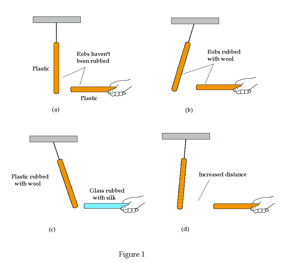
See Figure 1 below

In
Figure 1a there is one plastic rod hanging and one that is being held near the
end of the hanging rod, each of which has been untouched for some time. There is
neither an attraction nor a repulsion of the ends. We will say that the objects
are neutral. In Figure 1b each rod was rubbed with wool. Since each rod
has had the same experience, i.e. plastic rubbed with silk, then one might
expect that the rods have the same charge on them and should thus repel each
other. This is exactly what happens. In Figure 1c the hanging rod is plastic
rubbed with wool while the one being held is rubbed with silk. As seen in the
diagram these rods will subsequently attract each other. The signs of the charge
are not determined at this point. In Figure 1d we have the same situation as in
Figure 1b except that the distance has increased between them. We still have two
charged rods but now we know that the force between them decreases with
distance. Therefore in Figure 1 we can see which rods have zero charge, which
rods have the same charge and which rods have opposite charge with the knowledge
that like charges repel and unlike charges attract. Any charged object can pick
up small electrically neutral pieces of paper or bits of straw or dust. By the
definition given by Franklin, the charge on the glass rod when rubbed with silk
is defined as being a positively charged. Thus a plastic rod rubbed with
wool is negatively charged. Franklin discovered that the total amount of
charge in a closed system remains constant. This is known as the Law of
Conservation of Charge. The differential equation that describes this law is
derived below and results in Eq. (5). Thus if we rub a piece of glass with silk
and the glass becomes positively charged then it must be at the expense of
charges which are transferred from one object to the other leaving the silk
negatively charged by the same amount of the glass rod but with opposite sign.
If a plastic rod is rubbed with wool then the rod becomes negatively charged and
thus the wool must become positively charged by the same amount of charge but
the opposite sign. Thus the wool is positively charged. The wool being
positively charged will attract the silk, which is negatively charged.
Certain materials
permit electric charge to move from one region of a system to another region
while other materials cannot. The former materials are called conductors
while the later materials are called insulators. Any metal, such as steel
or copper, are conductors. Materials such as glass, plastic, nylon are
insulators. Suppose that we have a metal ball suspended by a nylon thread as
shown below in Figure 2
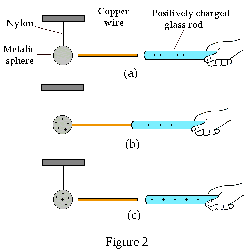
In
Figure 2a there is a small metallic sphere hanging from a nylon wire. The sphere
is uncharged and the glass rod on the right has been rubbed with silk to make it
positively charged. In Figure 2b the copper wire is used made to contact both
the sphere and the rod. This figure shows that some of the positive charge from
the glass rod has moved to the metallic sphere through the copper wire. The
nylon thread is an insulator that prevents the charge from bleeding into the
support structure from which the sphere is suspended. Figure 2c shows that the
sphere remains charged, as does the glass rod, which has less charge on it. The
total amount of charge has remained the same. Note: a wire was chosen to
conduct the charge onto the sphere. Here a wire refers to a rod whose
surface area is small compared to the sphere so that most of the charge is left
on the sphere and only an insignificant amount of charge is left on the wire.
An important
quantity in electrodynamics is current density J(r), which is
defined as having the magnitude dI
which is the amount of current flowing in the direction of the surface’s
normal vector, divided by the area dS
of the surface element. In order to shown that the current density has the value
J(r) = rv.
Figure 3 below allows us to visualize the information required in calculate this
expression.
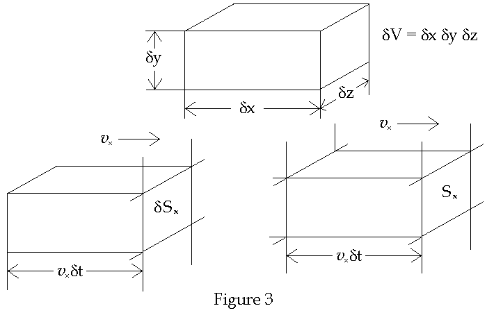
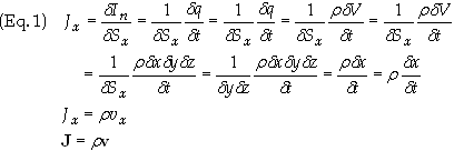
as was
intended to be shown. The definition of the current flowing through a closed
surface is
![]()
The
current I is related to r
and as such Eq. (2) becomes
![]()
QS
is the charge enclosed by the surface S, i.e. contained within the volume V.
The negative sign in Eq. (3) denotes the fact when a net current is flowing out
of the surface S the charge QS
enclosed by the surface decreases. Employing
the divergence theorem to Eq. (2) yields

Since
Eq. (4) is a general equation for charge density, current density and enclosing
surface it follows that the integrands must be equal, i.e.
![]()
Eq. (5)
is called the continuity equation; it is the differential form of the law
of conservation of charge as mentioned above.
Charging by Induction
Two
typical ways of charging something are by induction, conduction (as in Figure 2)
and by rubbing two materials together. We studied the first two ways above and
now give an example of charging by induction. Consider Figure 4 below
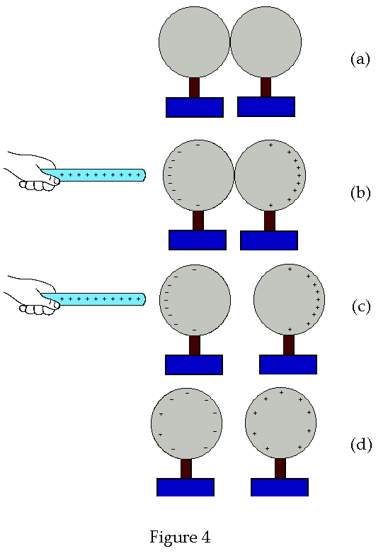
Figure
3a shows two spheres, located on top of insulated bases that are in contact with
each other. Figure 3b shows a rod that is positively charged brought near to the
spheres along a line that runs through the center of both spheres. The
positively charged rod attracts negative charge and repels positive charge as
shown in Figure 3b. In Figure 3c the spheres are separated while the charged rod
is still near. In figure 3c the rod is taken away and we are left with two
charged spheres.
Coulomb's
Law
In
1795 Charles A. de Coulomb’s reported the basic experiments of electrostatics.
The results of these experiments have been analyzed and used to
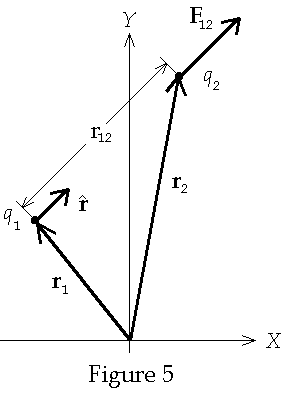
formulate which is now known as Coulomb’s Law. This law states that the
force exerted on charge q2
by charge q1,
F12,
is given by
![]()
![]() is a unit vector pointing from point charge 1 to point charge 2, as shown in
Figure 5 below
is a unit vector pointing from point charge 1 to point charge 2, as shown in
Figure 5 below
Let
an object with a positive charge of charge dq
whose size and mass are so small as to not significantly effect the position of
the source. Such a charge is called a test charge. Note: This is
an ideal definition and must be used with caution since charge, in general, come
in the form of a number of very small discrete charged particles having both
negative and positive charges. The negatively charged particles, which have the
smallest measured charge, in a current carrying wire is the electron and
as such no charge can have a charge less than that of an electron. The ions that
make up the lattice structure of the wire are the positively charged nuclei of
the atoms, which make up the structure of the wire. Nuclei are composed of a
number of positively charged particles called protons. So this model of smaller
and smaller charge dq
has a lower bound. With this limitation understood, the Electric Field at
the location r is defined as the limiting value of the ratio of electric
force on the test charge dq
due to a source charge q which is the source of the force Ft
on the test charge as dq
®
0, i.e.
![]()
From
Coulomb's law we find that the electric field of a point charge q located
at r of a point charge is given by

If more
charges are present then the electric field at any point in space is given is
found by the experimental property that the electric field satisfies the principle
of linear superposition. For a system of n particles located at ri, i
= 1, 2, … , n, the vector sum gives the electric field at the point r.

Eq. (9)
is interpreted as follows; Ei
is the electric field that would be measured in the absence of all charges
except qi.
The electric field E, as defined in Eq. (9) is the electric field that is
measured in the presence of all i particles. E is simple called
the electric Field.
If the charges are so
small and so numerous and that they can be described by a charge density r(r’)
then the sum in Eq. (9) is replaced with the integral
![]()
Recall
the vector identity
![]()
Substituting
Eq. (11) into Eq. (10) gives

FE(r)
is referred to as the electric scalar potential and has the value
![]()
The curl
of E vanishes since
![]()
The
right hand side of Eq. (14) follows from another vector identity which holds
that Ñ´ÑFE(r)
= 0 for all possible values of FE(r).
We know from vector calculus that a static electric field E(r)
whose curl is zero is a conservative field which means
![]()
For all
paths C. This implies that the integration has the same value between two
distinct points that is independent of the path of integration chosen.
Field Lines
An
important concept in electrodynamics is that of field lines. Consider a
point charge. Draw the electric field vector as shown in Figure 6 below
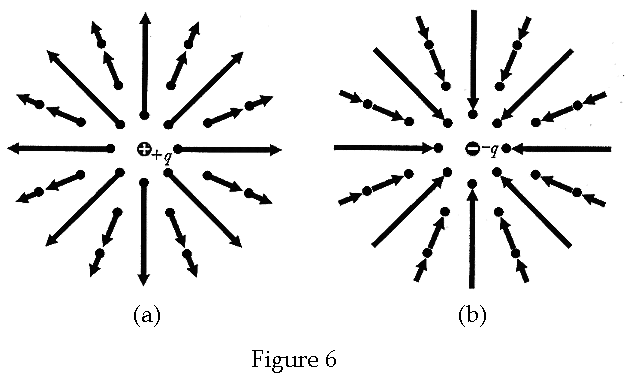
The
length of the electric field vectors represents the magnitude of the field at
that point. The direction of the arrow represents the direction of the force
that would exist on a test charge if placed at that point in the field. Figure 5
is a graphical representation of the electric field. In Figure 5a the source
charge is positive and thus the field vectors point away from the source. In
Figure 5b the source charge is negative and the field vectors point towards the
source charge.
Alternatively,
the electric field can be represented graphically using field lines.
These are lines drawn in such a way that, at any given point, the tangent to the
line is parallel to the field at the point and directed in the same direction as
the electric field. This is shown for a positive point charge in Figure 7 below
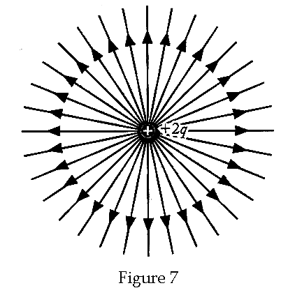
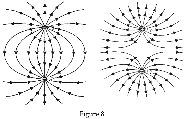
The
density of the field lines represents the intensity of the field in that region.
The next example is that of two charges. On the left side of Figure 6 below the
electric field on the left shows two charges of opposite sign while the right
side the charges are of the same sign
The flux of a field E through a surface is defined as the
normal component of the field vector times the surface area. There are field
lines passing through every point on the surface area and it is assumed at this
stage that the electric field is uniform over the surface that is assumed to be
flat. Otherwise for curved surfaces or flat surfaces for which the electric
field varies over must be broken up into infinitesimal surface elements so that
the field is uniform over that element has the same value for all practical
purposes. The product is then integrated to yield a finite value. The surface
vector S is defined as having the magnitude of the area and the direction
normal to the surface. Since there are two such normal directions this vector is
not unique. Which direction is chosen will depend on the problem at hand. See
Figure 9 below. Note that the vector S is not shown
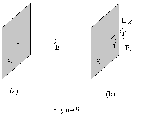
For a
flat surface over which the magnitude and direction of the field lines is normal
to the surface as well as being constant over the surface the flux of the vector
field E through the area S in Figure 9a is easily seen to be
![]()
In
Figure 9b the situation is a bit more complicated. The vector field at all
points on the surface has the value F but is not normal to the surface.
The flux is then given by the product of the surface area times the magnitude of
the normal component of F. The flux is therefore given by
![]()
For a
curved surface this readily generalizes to
![]()
Gauss’s
Law
The
integral in Eq. (5) is not always the most suitable form for the evaluation of
the electric fields. Another method for finding the electric field is provided
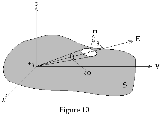
by Gauss’s Law. We begin the derivation of Gauss’s law first consider
a point charge at the origin of coordinates within a closed surface S as shown
below in Figure 10
We now
wish to find the electric flux over the entire surface S. Our first step is to
evaluate E·dS.
For a point particle this becomes

The
second term on the far right of Eq. (7) is
![]()
dW
is a solid angle
subtended by dS. Eq. (19) can now be expressed as
![]()
We now
integrate this over the entire surface to obtain the total flux of the electric
field passing through the surface. We use the fact that the integral of the
solid angle over an arbitrary surface has the value of 4p

Eq. (22)
was derived on the assumption that the surface S enclosed the charged particle.
If the charge were outside the surface then the total flux would be zero. If
there are n charged particles enclosed by the surface then it is
immediately apparent that
![]()
For a
continuous charge distribution we have

Eq. (24)
is known as Gauss’s Law. In order to place this in the form of a
differential form recall the divergence theorem which states that, for any well
behaved vector field C that
![]()
Applying
this to Gauss’s Law gives

Since
the volume enclosed by the surface is arbitrary it follows that the integrands
must be equal. We therefore have the differential form of Gauss’s Law.

The
result in Eq. (18) is often referred to as the differential form of Coulomb’s
Law.
Biot-Savart
Law
The
ancient Greeks knew that certain minerals called loadstones could attract
iron objects. Chinese navigators were using loadstone compasses. Today we would
refer to materials that display such properties as magnets. If a small
bar magnet is placed on a cork and then allowed to float in water then one end
of the magnet would point in the general direction of geographic north pole
while the other end would point to the geographic south pole. The north-seeking
end of the magnet is now referred to as the north magnet pole while the other
end is referred to as the south magnetic pole. Given any object, which displays
magnetic properties, all of them will have both a north magnetic pole and a
south magnetic pole. And regardless of how the object is cut the results will be
two magnets each having both a north pole and a south pole. About the year 1,600
A.D. William Gilbert recognized that the compasses work because the earth itself
is a magnet. Thus the geographical North Pole is in the general direction of the
earth’s magnetic south pole and the geographic South Pole is in the general
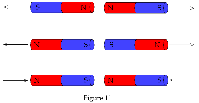
direction of the earth’s north pole! A bar magnet is shown below with both
North (N) and South (S) labeled. Notice that like poles repel while unlike poles
attract. See Figure 11 below
In the midst of a classroom lecture demonstration in
1918 the Danish scientist Hans Christian Oersted discovered that if a
current were established in a wire, by connecting it to a battery, a nearby
compass would needle would turn. The compass thus responded as if it were in a
magnetic field. Oersted’s discovery that magnetism is caused by an electric
current will be the starting point for analyzing the magnetic field in this
section. The concept of what Oersted observed in his lab is shown below in
Figure 12
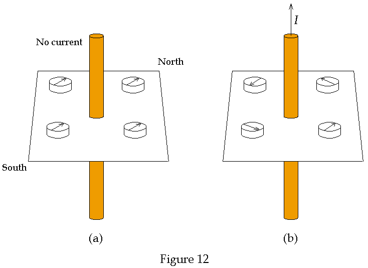
In
Figure 12a there is no current in the wire and the compasses placed around the
wire point in the direction of North. In the figure the compass arrows point in
the direction of the geographic North Pole and thus represent the north
magnetic. In Figure 12b there is a current in the wire and magnets placed
equidistance from the wire will exert the same value of torque that all other
identical magnets will experience at the same distance. If compasses are place
in a circle around the wire they will point in a direction tangent to the
circles and in the direction given by the right hand rule. The right hand
rule refers to the idea that if the wire is carrying a current and a person
grabs hold of the wire with their thumb pointing in the direction of the wire
then the fingers curl around the wire in an anti-clockwise direction.
If more compasses are added, each at the same distance from the current
carrying wire, then they appear to form a circle as shown in Figure 13 below
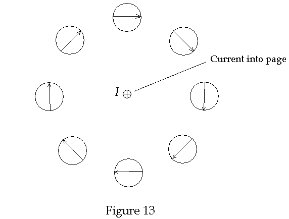
It is
clear from Figure 13 that if more and smaller compasses were placed around the
wire then the diagram would look more and more like a circle. Such a line is
called a magnetic field line (even if the line is curved and not straight). The
magnetic field lines are imaginary lines such that a tangent to the field line
is in the direction of the magnetic field and the closer the lines are together
the greater the strength of the magnetic field. The idea of magnetic field lines
originated with Michael Faraday. Faraday constantly thought in terms of
lines of force. As Faraday wrote
I cannot refrain from again expressing my conviction of the truthfulness of the representation, which the idea of lines of force accords in regard to magnetic action – i.e. all that is not hypothetical appear to be well and truly represented.
The next
step in history was when Andre-Marie Ampere who, after hearing of Oersted’s
discovery showed at a meeting exactly a week later that two parallel wires
carrying currents in the same direction attract each other while two parallel
wires carrying currents in the opposite direction repel. This is illustrated in
Figure 14 below
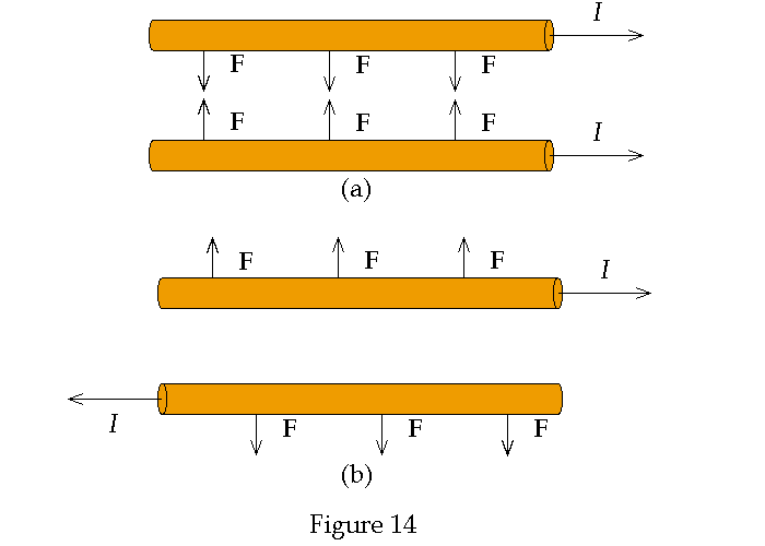
From
what has been shown so far we can now understand what the magnetic field around
a straight conducting wire looks like. See Figure 15 below
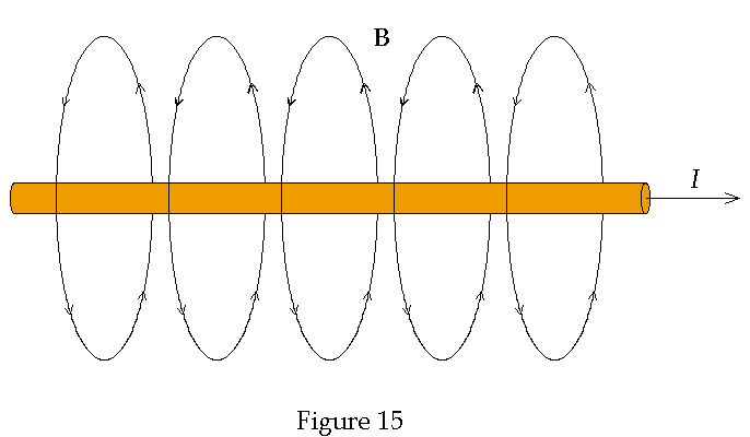
Since a
current consists of moving charges Ampere’s experiment implied that a magnetic
field exerts a force on a moving charge.
Consider the magnetic field of a long current carrying wire and a charged
particle moving in the direction of the current as shown in Figure 16a
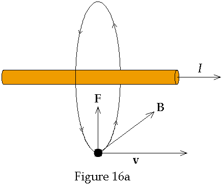
In this
case the magnetic field is tangent to a circle that is in a plane where the
surface normal vector is parallel to the direction of the current. The straight
wire passes through the center of the circle. The resulting force is directed
radially inward and has the magnitude F = qvB. If the direction of
the charge is opposite the direction of the current as shown in Figure 16b shown
below
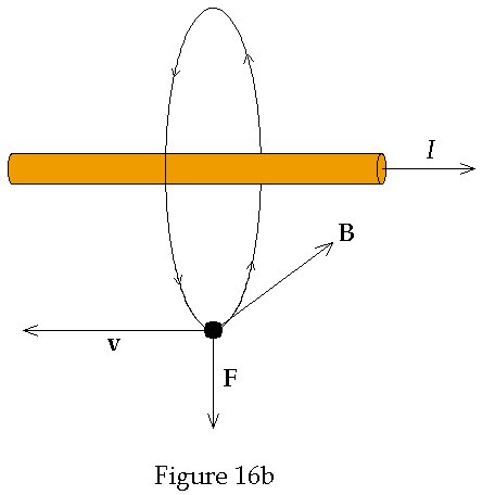
The
magnitude of the force is the same but is now directed in the opposite
direction, i.e. radially outward. In the case where the velocity is radially
inward as in Figure 16c then the force is anti-parallel to the current
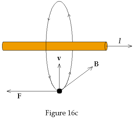
If the
direction of the velocity is radially outward then force on the particle is in
the direction parallel to the current as shown below in Figure 16d.
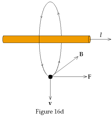
If the
velocity is not perpendicular to the magnetic field then only the perpendicular
component of the velocity to the magnetic field will apply. In all cases the
force is always directed perpendicular to the plane containing the velocity and
field vectors. Thus the magnetic force has the general value of
![]()
In 1820 Biot and Savart first and later during the years 1820-1825
Ampere, in more elaborate and thorough experiments established the basic
experimental laws relating the magnetic field B to the currents and
established the magnetic force law between two currents. [Jackson p. 175]
Since a compass/magnetic dipole m
will experience a torque N when placed in a magnetic field the magnetic
field B is sometimes defined as
![]()
If dr’
is an element of length (pointing in the direction of current flow) of a
filamentary wire that carries a current I and r is the coordinate
vector from the element to an observation point P as shown in Figure 17
below
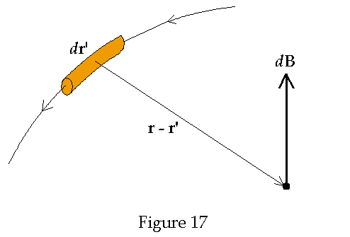
The
magnetic field strength was found to be

Eq. (30) is called the Biot-Savart Law. The total magnetic field B is found by integrating Eq. (30) over the entire path of the current. The result is
![]()
For the
general case of a finite current density J(r) the line integral in
Eq. (31) becomes a volume integral

Recall again the identity in Eq. (11) above. Substituting Eq. (11) into Eq. 31 yields

Using
the vector identity
![]()
gives

That
last term on the right side vanishes since J(r’) is a function
of r’ while Ñ
is a function of derivatives in terms of the unprimed coordinates. Substituting
Eq. (33) into Eq. (31) gives

where
![]()
is
known as the magnetic vector potential. The equation B = Ñ´A
is usually regarded as a formula for finding B if A is known.
Taking the divergence of Eq. (34) is zero since the divergence of the curl of
any vector vanishes. We are therefore left with
![]()
This is
the first equation of magnetostatics and corresponds to Ñ´E
= 0. The Helmholtz
Theorem requires only that additional knowledge of Ñ·A
to uniquely, up to an arbitrary the gradient of an arbitrary scalar function,
determine A. Taking the divergence of A gives
![]()
Eq. (37)
is known as the Coulomb gauge. The general form of A, at least in
magnetostatics, is
![]()
To find
the Ñ´
B we take the curl
of Eq. (34)

Using
the vector identity
![]()
in Eq.
(40) gives

The
first integral on the right vanishes. To see this, and to simplify the last
integral on the right, we employ the identity in Eq. (11) and, the following two
vector identities
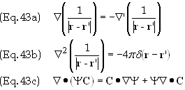
Eq. (42)
becomes
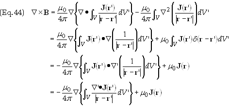
The
integral integrand vanishes due to the fact that we are only considering
magnetostatic scenarios for which the charge density is not an explicit function
of time. Therefore Eq. (5) tells us that Ñ’·J(r’)
= 0. We are therefore left with
![]()
This is
the differential equation form of the Biot-Savart law in the case of
magnetostatics.
The
integral form of Eq. (44) is known as Ampere’s Law. To obtain the
integral form we take the normal component of Eq. (44) and integrate over an
open surface S that is bounded by a closed curve C. This is shown in
Figure 18 below
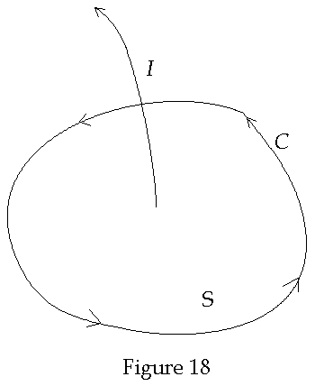
The
integral of the normal component Eq. (44) is
![]()
Applying
Stoke’s theorem to Eq. (45) yields

Ienc
is the total current flowing through the surface bounded by C.
Faraday’s
Law of Induction
Induced
Electromotive Force (EMF):
In 1831 Michael Faraday found that a time varying magnetic field
near a coil would induce a current in the coil. Three examples are shown below
in Figure 19 below
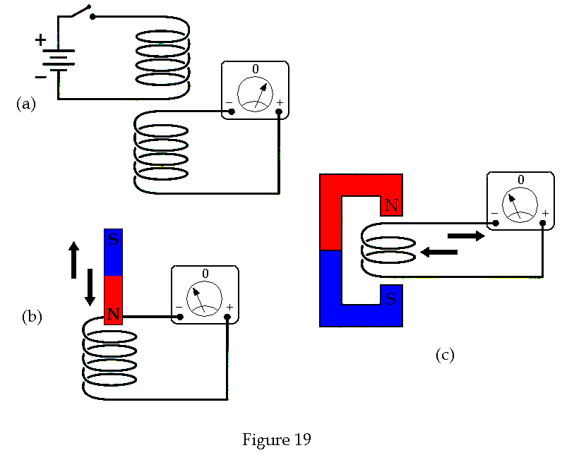
In
Figure 19a the meter measures a current only when the switch is turned on or
off. In Figure 19b the meter measures a current when either the magnet is moved
in and out of the coil. In Figure 19c the meter measures a current when the loop
is passed into and out of the field between the N and S poles of the magnet.
Currents produced in this way are called induced currents. They occur
only when there is a time varying magnetic field in the coils. The induced force
is a result of the magnetic force Fmag
= qv´B
Motional
EMF:
If a conductor is moved through a magnetic field then the free charges inside the conductor will experience a magnetic force. The charges will then migrate through the conductor until it can go no farther or it will complete a path and the force on the conductor will maintain the motion of the conductor through the magnetic field so that current will continue to flow. The induced current is called a motional EMF. Note: EMF is not a force.
Induced EMF:
The induced emf E
is is defined as
![]()
The line
integral is taken around the closed path C. Faraday’s law is given by
![]()
where
![]()
is the
total magnetic flux through any surface bounded by C. Using this result
Faraday’s law becomes

Since
Eq. (51) is a general statement and thus holds for all possible curves it then
follows that
![]()
Eq. (52)
is the differential form of Faraday’s Law
The laws
of electrodynamics as stated above in Eq . (5), (14), (45), (52) were derived
from steady observations. That they
are inconsistent can be seen by taking the divergence Eq. (45), which then gives
![]()
This
relation is only valid when the charge density is not an explicit function of
time. Otherwise, by Eq. (5), the Ñ·J(r,
t) will not be zero in general. To compensate for this, Maxwell realized
that the divergence relation in Eq. (5) could be modified using Coulomb’s Law
as follows

The term
![]()
is known
as the displacement current and whose physical meaning is that a time
varying electric field “causes” a magnetic field. The term cause has
been placed in quotes since all that can really be said is that when there is a
time-varying electric field then there also exists a magnetic field. Eq. (45)
now becomes

Eq. (56)
is Ampere’s Law in its most general form.
Vector
and Scalar Potentials
The
expressions above for both the electric scalar potential and the magnetic vector
potential may be combined to find an explicit expression for the electric field
in terms of these potentials. Substitute Eq. (35) into Eq. (52) to obtain

Eq. (58)
means that the term on the right inside the parentheses must be the gradient of
a scalar, which we’ll call Y
for the moment. Eq. (57) now takes the form

In
magnetostatics, when A is zero, we see that y
is really FE,
i.e. the electric scalar potential. Thus Eq. (58) becomes
![]()
Lorentz
Force
The
total force on a charged particle is found to be the sum of the electric force
and the magnetic force, i.e.
![]()
This
force is known as the Lorentz force law. However this is not a
true law in the literal sense since it can be derived from the other laws above
using special relativity.
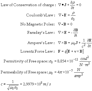
Summary
of Maxwell's Equations
(in MKS/SI units)”
References:
[1] Electromagnetics,
John D. Krauss, McGraw-Hill, (1984), pg. 1.
[2] A
History of the Theories of Aether & Electricity, Sir Edmund Whittaker, Dover
Pub., (1989 – originally published in 1951 and 1953), page 33.
[3] Ref.
2, pp. 34-35.
[4] The
Electromagnetic Field, Albert Shadowitz, Dover Pub., (1975), pg. 8.
[5] Ref.
1, pg. 2.
[6] Ref.
1, pg. 3.
[7] Ref. 2, pg. 172.