Define
the reactance and impedance of a coil carrying an alternating current.
Distinguish between the impedance and resistance of a coil and explain
how they are related.
4
marks
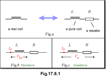
A coil in reality has resistance. It can be
regarded as a pure coil in series with a resistor as shown in Fig.a.
1
The reactance of the coil concerns with
the pure inductor. It is defined as the ratio of the peak voltage across
the pure inductor to the peak current through it:
see Fig.b
1
The impedance of the coil concerns with
the whole device, including the resistance. It is defined as the ratio
of the peak voltage across the coil to the peak current through it:
see Fig.c
1
The impedance Z of a device limits the
alternating current for a given a.c. voltage. The resistance R limits
the direct current for a given d.c. voltage. They are related through
1
b.
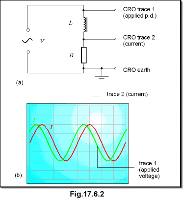
Outline
an experiment to investigate the phase relationship between the applied
voltage and current in a circuit which consists of a coil and a known resistance
connected in series. Show how the reactance of the coil could be estimated
from the results of the experiment.
6
marks
2
The CRO used is double beam. One of the y-input
is connected across the two components and displays the applied p.d. The
other y-input is connected across the resistor and displays the current.
1
Results shows that the applied voltage leads
the current. The phase difference between V and I can be calculated by
measuring the distance x of separation between the two peaks and
the distance T for one period. Then, apply
1
The reactance of the coil is related to the
resistance R and phase difference f by
2
c.
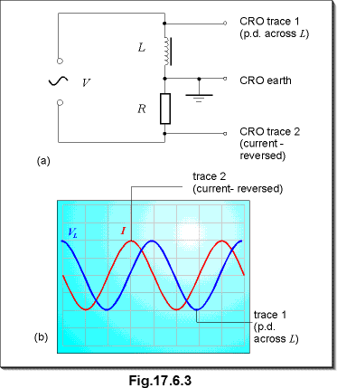
Using
the set up in (b), state what changes you would make so that the phase
relationship between the p.d. across the coil and the current could be
demonstrated.
2
marks
1
In this set up, the p.d across the coil and the p.d. across
the resistor are measured directly. However, since the earth terminal of
the CRO is at the middle of the two components, the trace that shows the
p.d. across the resistor is effectively in anti-phase with the actual current
through the coil. Thus, the current is lagged behind the voltage across
L by 90o.
1
d.
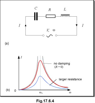
A
coil of inductance L and resistance R is connected in series with a capacitor
C and a variable frequency sinusoidal oscillator of negligible impedance.
Sketch qualitatively how the current in the circuit varies with the applied
frequency and account for the shape of the curve. Sketch on the same axes
the curve you would expect for a considerably larger value of R, the values
of L and C being unchanged.
4
marks
2
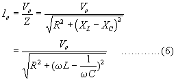
The current through the circuit is
1
When the angular frequency is
the current is the largest. We say that resonance occurs.