| Contents | ||
|---|---|---|
| Development of Binoculars | Binocular Characteristics | Choosing Binoculars
Using Binoculars Testing Binoculars Galileo Galilei Properties of Glass |
The Development of Binoculars and TelescopesInvention of LensesAn inability to focus the eyes on close-to objects is a common problem in later life, and makes reading in particular very difficult. The Franciscan friar Roger Bacon wrote in 1267 of a solution to this problem, using sections of glass spheres which could be laid over a written page to make the letters larger. By the end of the thirteenth century Italian craftsmen were making thin glass sections and putting them in frames which could be worn in front of the eyes. These reading glasses were convex, that is thicker in the middle than at the edges, and thus the same shape as lentils. The Latin for lentil is lens, hence the glasses became known as lenses. | ||||||||||||||||||||||||||||||||||||||||||||||||
| Back to Contents | ||||||||||||||||||||||||||||||||||||||||||||||||
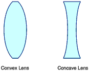
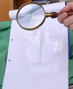
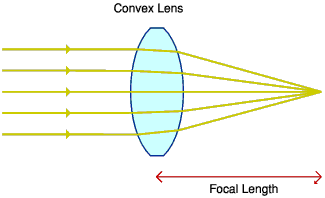
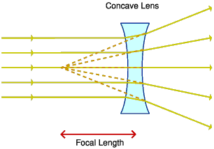
Types of LensFigure 1 shows the shapes of convex and concave lenses. A convex lens (as used in a magnifying glass) forms what is known as a real image of an object by bringing rays of light to a focus on the other side of the lens. A real image is one which can be projected onto a screen and this property can be demonstrated by holding a magnifying glass facing a bright window then placing a sheet of white paper about 20 to 30cm behind the lens and moving it to and fro until the outline of the window is visible on the paper, as in figure 2. It will be noticed that the image is upside down and blurry towards the edges, and that there are coloured fringes around areas of high contrast, especially if the lens is made of plastic rather than glass. The distance between the lens and the paper when the image is focussed is approximately the focal length of the lens. The path of parallel rays of light, as from a small distant light source, through a convex lens is shown in figure 3. By contrast, when light rays pass through a concave lens they emerge diverging, as if from a point on the same side of the lens as the light source. See figure 4. Because the light rays have not really passed through the focal point, but only appear to have, if a screen were placed there no image would be formed. A concave lens is said to form a virtual image and to have a negative focal length. | ||||||||||||||||||||||||||||||||||||||||||||||||
| Back to Contents | ||||||||||||||||||||||||||||||||||||||||||||||||
The First BinocularsThe first binoculars were built in December 1608 for the Assembly of the States General of the Netherlands by Hans Lippershey. He was a spectacle maker from Middleburg in Zeeland and had discovered that a convex lens and a concave lens could be combined to produce a magnified image of a distant object - a simple telescope. Lippershey offered his telescope to the States General on 2nd October 1608, and they requested a version to be used by both eyes, for military purposes. Three sets of binoculars (meaning roughly 'two eyes') were duly delivered but do not seem to have been a huge success with the military, perhaps because they would have had low magnification and poor image quality. Lippershey requested a patent on his invention but it was refused on the grounds that it was not sufficiently novel. Indeed there is some doubt as to whether Lippershey really was the first to combine two lenses into a telescope. Certainly by early 1609 small 'spyglasses', which we would call telescopes, were widely on sale in Paris. Binoculars however were seldom made because they required much more than twice as much work as a telescope, to manufacture two precisely matched pairs of lenses and fix them in accurate alignment. Considering that lenses had been available for several centuries, it is somewhat surprising that no-one had discovered the telescope before 1608. Possibly the reason is that to obtain useful magnification the eyepiece lens needs to have a short focal length and thus a large amount of curvature, and lens-grinding technology was not capable of producing such lenses of sufficient quality to yield a clear image. | ||||||||||||||||||||||||||||||||||||||||||||||||
| Back to Contents | ||||||||||||||||||||||||||||||||||||||||||||||||
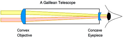
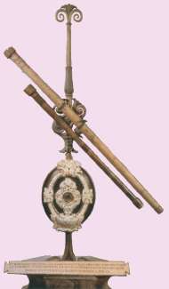
Early Telescopes - Galilean OpticsThe Italian physicist Galileo Galilei learnt of Lippershey's invention in 1609 and set about building a telescope for himself, eventually producing around one hundred, with magnifications from three times up to about thirty times. With his telescopes Galileo observed the craters on the Moon, the four largest satellites of Jupiter, and began a revolution in the science of astronomy. These early telescopes consisted of just two lenses, a convex lens at the front, called the objective, and a concave lens at the eye end, called the eyepiece. These were held in position by a tube made of rolled paper or copper. Their general form and the path of light rays through them is shown in figure 5. Galileo's lenses were only curved on one side and flat on the other. This was to reduce the amount of difficult shaping of the lenses needed. A peculiarity of Galilean type telescopes, using a concave eyepiece, is that the light forming any part of the image has only passed through a small area of the objective lens. The result is that the telescope has a very small field of view unless the magnification is low, and this field of view depends on the diameter of the objective. Looking through a Galilean telescope always gives the impression of looking down a narrow tube, and Galileo must have had great difficulty in even finding celestial objects in the sky with his more powerful telescopes. Figure 6 shows two of his telescopes which have survived. This very simple design of telescope, using just two lenses to produce an upright image, is still used in low magnification 'opera glass' type binoculars since very short tube lengths are possible. It is always known as the 'Galilean' design, rather unfairly to Hans Lippershey. | ||||||||||||||||||||||||||||||||||||||||||||||||
| Back to Contents | ||||||||||||||||||||||||||||||||||||||||||||||||
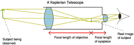
Improved Telescopes - Keplerian OpticsThe next step in the evolution of the telescope was made in 1611 by the astronomer Johann Kepler, whose design used a convex lens for the eyepiece as well as for the objective, as shown in figure 7. The principle of operation of a telescope can be seen more clearly in the Keplerian than the Galilean. The Keplerian design gives a wider field of view than the Galilean, and one which does not depend on the size of the objective lens. It also produces a brighter image at high magnifications because light from all parts of the field of view passes through the whole area of the lens. Unfortunately Kepler's design gives an upside-down image. This was not really a problem for astronomers (a star looks pretty much the same any way up) and some small astronomical telescopes still use a derivative of the Keplerian design today, but it was a distinct drawback for terrestrial use. | ||||||||||||||||||||||||||||||||||||||||||||||||
| Back to Contents | ||||||||||||||||||||||||||||||||||||||||||||||||
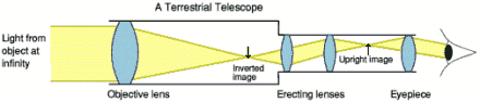
Terrestrial TelescopesA solution to the problem of inverted images was found by Anton Maria Schyrle of Bohemia, who added two extra lenses to turn the image the right way up, as shown in figure 8 The tube length of a Galilean telescope equals the focal length of the objective minus the focal length of the eyepiece. For a Keplerian the tube length is the focal length of the objective plus the focal length of the eyepiece. The total length of a terrestrial telescope is the sum of the focal lengths, plus a little more for the erecting lenses, which makes the whole assembly quite cumbersome and is the reason why portable ones are often made 'telescopic', i.e. consisting of several sections which slide into each other. | ||||||||||||||||||||||||||||||||||||||||||||||||
| Back to Contents | ||||||||||||||||||||||||||||||||||||||||||||||||
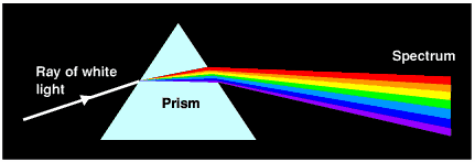
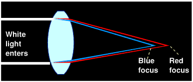
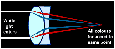
Aberration - Refinements to Telescope DesignA simple Keplerian or terrestrial telescope as drawn above, with single convex lenses for objective and eyepiece, actually suffers from several defects. A much greater problem is chromatic aberration. No doubt everyone has seen how a glass prism can split white light up into the colours of the rainbow, as in figure 9. The spectrum is produced because when light is bent (refracted) in passing from air to glass or glass to air, blue light is bent more than red light. Unfortunately a lens acts like a thin prism with the result that blue light is brought to a focus closer to the lens than red light, as in figure 10. The effect of chromatic aberration in a telescope is that it is impossible to get all the colours in focus at the same time so that anything seen through early telescopes had a coloured halo around it and appeared blurred. Both spherical and chromatic aberrations can be reduced by making the focal length of the objective lens very long, so that it needs to be only slightly curved. In the early eighteenth century it was common for even small aperture astronomical telescopes to have tube lengths of ten metres or more, which made them extremely difficult to aim, or even to keep them from bending. For a long time chromatic aberration was thought intractable but in 1733 an Englishman, Chester Moor Hall, designed a compound lens consisting of two different types of glass, which almost eliminated the false colours. His idea was developed by John Dolland and his achromatic (colour-free) lens was patented in 1758. A so-called achromatic doublet consists of a convex lens made of crown glass and a concave lens made of flint glass, usually cemented together. The outer curvature of the convex lens is greater than that of the concave lens so that overall the combination is still convex. Flint glass spreads light out into a spectrum more than does crown glass (it is said to have a higher dispersion) but because it is in the form of a diverging lens it largely cancels out the dispersion of the convex crown glass lens. See figure 11. Strictly speaking such an achromatic lens only exactly cancels chromatic aberration at two wavelengths, though it is greatly reduced at all other wavelengths. As a bonus it can also correct for spherical aberration. It is possible to reduce chromatic aberration to negligible levels using a three-component 'apochromatic' lens, but obviously manufacturing three precisely matched lenses is expensive. | ||||||||||||||||||||||||||||||||||||||||||||||||
| Back to Contents | ||||||||||||||||||||||||||||||||||||||||||||||||
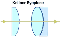
EyepiecesTelescope eyepiece lenses too underwent changes. A single convex lens gives a fairly narrow field of view and introduces its own spherical aberration. Several alternative designs are in use but one of the most popular today in moderate priced equipment is the Kellner, which uses two separated 'plano-convex' lenses to correct for spherical aberration, one of which is an achromatic doublet since otherwise some chromatic aberration would occur in the eyepiece. See figure 12. | ||||||||||||||||||||||||||||||||||||||||||||||||
| Back to Contents | ||||||||||||||||||||||||||||||||||||||||||||||||
Further Developments in BinocularsThe oldest binocular still in existence is a Galilean type made for the Grand Duke Cosimo III de Medici in the 1670s and is essentially just two Galilean telescopes side-by-side in one case. There seems to have been little progress in binocular design for a long time, probably because it was so difficult to produce two exactly matched telescopes, with the same magnification, and fix them precisely parallel to each other. Telescopes were widely available by the eighteenth century but binoculars would sometimes have been preferable:
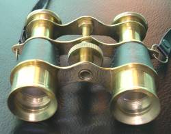
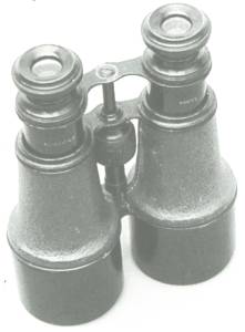
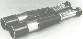
In the 1820's binocular 'opera glasses' or 'theatre glasses' began to be produced in significant numbers. These were still based on Galilean optics (remember the advantage of a short optical tube length), with either individually extending eye-tubes, or both eyepieces joined together and moved by a central screw for focussing. These opera glasses were compact and frequently elegantly finished in ivory and gilt, but their magnification was only 2 to 3 times so that the field of view remained reasonably wide. Figure 13 shows a recently-made pair of opera glasses. In the second half of the nineteenth century so-called 'field glasses' also became popular. These were similar to opera glasses but with higher magnification, about 5 times, and usually achromatic doublet objective and eyepiece lenses. Figure 14 shows a French field glass from around 1910. All binoculars up to this point had used the Galilean optical system with its drawback of a restricted field of view at higher magnifications. Schyrle's design of terrestrial telescope had been improved by Joseph Fraunhofer and towards the end of the nineteenth century binoculars began to appear which were two terrestrial telescopes mounted side by side. These allowed a wide field of view even at high magnifications but required a fairly long and unwieldy tube length, as in figure 15. | ||||||||||||||||||||||||||||||||||||||||||||||||
| Back to Contents | ||||||||||||||||||||||||||||||||||||||||||||||||
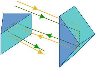
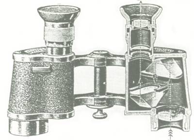
Prismatic BinocularsThe phenomenon of total internal reflection allows a glass prism to act as a mirror. In the 1850s an Italian artillery officer named Ignazio Porro devised a method of combining two right-angled prisms in such a way that an image was reflected four times off the angled faces and in the process inverted. If the image were upside down to start with it would now be the right way up. Porro patented a telescope using his combination of prisms to yield an upright image but the limitations of optical glass at that time meant it was not widely used. Figure 16 shows the light path through a pair of Porro prisms. A bonus with the Porro prism design was that the light path was 'folded' so that the telescope could be much shorter than a conventional terrestrial telescope, and there were attempts to use this advantage in binoculars also. Ernst Abbe of the University of Jena independently discovered the principle of inverting prisms in 1870 and he collaborated with the chemist Otto Schott to develop better quality optical glass. By 1893, in partnership with the Carl Zeiss optical instrument works, Abbe had built his first prismatic binocular. The physicist Hermann Helmholtz had studied stereoscopic vision and found that the separation of the human eyes means that each eye has a slightly different view of a scene, and the brain uses this information to help judge distance. It can be seen from figure 16 that the inverting prisms also displace the light path sideways and Abbe designed his binoculars such that the objective lenses were further apart than the eyepieces so that the stereoscopic effect was enhanced and thus it was possible to judge relative distances better. The shape of the first Zeiss prismatic field glass of 1894 (figure 17) is recognisable as the form of standard binoculars today. The optical system was essentially that of a Keplerian telescope which meant that a wide field of view and high magnifications could be achieved, which in turn meant that focussing was more critical. Early designs had individually screw-focussed eyepieces while later designs used a central focussing wheel for both eyepieces with separate slight adjustment to one to allow for any difference between the user's eyes. Zeiss were granted a patent for their Porro-prism design and hence this optical layout is still often called Zeiss centre focus or ZCF. Within a few years many other binocular manufacturers had introduced their own prismatic versions, though to avoid infringing Zeiss's patent their objectives were usually offset above the eyepieces rather than to the side. After the patent expired in 1908 the Zeiss body shape as in figure 17 became almost universal until towards the end of the twentieth century. | ||||||||||||||||||||||||||||||||||||||||||||||||
| Back to Contents | ||||||||||||||||||||||||||||||||||||||||||||||||
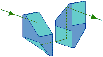
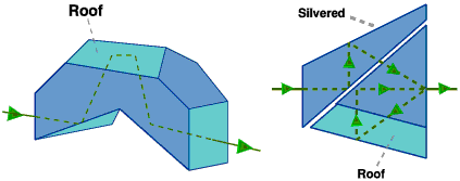
Alternative Prism DesignsTwo other prism designs are sometimes used in binoculars. Porro devised another form of image-erecting prism pair using prisms of a more complicated shape, as shown in figure 18. Sometimes called 'Porro-Abbe' prisms, these can give a slightly more compact binocular, especially if the two facing prism faces are cemented together, but are more expensive to manufacture. Another type, which was first made in 1897 but did not become popular until the 1980s, is the roof prism design. These contain a prism, or pair of prisms, one of whose faces is shaped like a barn roof to perform the function of turning the image upright. There are several variations but one of the simplest is the Dialyt prism used by Zeiss and illustrated in figure 19. Most current roof prism binoculars utilise the Schmidt design, also shown in figure 19, which is a more complex shape and consists of two prisms, with one side of the first prism silvered so that it reflects light, since the angle at which light meets the surface is less than the critical angle. Binoculars using roof prisms are easily recognised because their eyepieces and objectives are in a straight line rather than offset, resembling a shorter version of the twin telescope binocular of figure 15. | ||||||||||||||||||||||||||||||||||||||||||||||||
| Back to Contents | ||||||||||||||||||||||||||||||||||||||||||||||||
Coated OpticsIt is an unavoidable fact of nature that whenever light passes from air into glass or vice versa, although most passes through, a small proportion (about 4%) is always reflected. Binoculars have ten or more air/glass interfaces in the light path which means that a significant proportion of the light which enters the objective lenses never makes it out of the eyepieces. This not only results in the image being dimmer but some of the reflected light is scattered inside the optics and reduces the contrast of the final image. However by 1939 Zeiss had found a partial solution to this problem. They found that by evaporating an extremely thin coating, about 150 millionths of a millimetre thick, of magnesium fluoride onto the surface of lenses the amount of reflection could be greatly reduced. This is because the proportion of reflected light depends on the difference in refractive index at the interface, and magnesium fluoride has a refractive index intermediate between that of glass and air. (Also any light which is reflected tends to be cancelled out by destructive interference within the coating.) | ||||||||||||||||||||||||||||||||||||||||||||||||
| Back to Contents | ||||||||||||||||||||||||||||||||||||||||||||||||
Binocular CharacteristicsBinoculars are generally described according to their body style, objective lens diameter, and magnification. Other important features are the field of view and exit pupil diameter. Some of these details are usually printed on the binoculars themselves, as in figure 21. | ||||||||||||||||||||||||||||||||||||||||||||||||
| Back to Contents | ||||||||||||||||||||||||||||||||||||||||||||||||
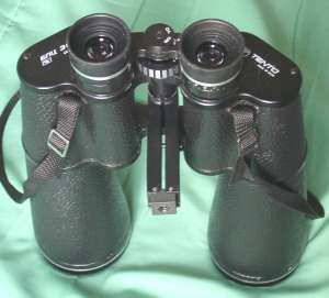
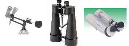
Body ShapeBinoculars come in several different shapes, often identified by letter codes: Zeiss Centre Focus or ZCFZeiss pattern binoculars have their objective lenses further apart than their eyepieces and are the 'traditional' binocular shape. There are actually two varieties, the 'German style' in which the tubes holding the objective lenses are separate and screwed into the prism housing, and the 'American style' where the objective tube and prism housing are cast in one piece. See figures 22 and 23. Figure 22 - German body style binoculars, 12x50 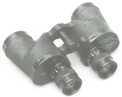 Figure 23 - American body style 6x30 binoculars. These also have individually focussed eyepieces and were made for the US Navy in 1943. The threaded connection for the objective tubes can be a weak point so the American style tends to be more robust. The German style is known as ZCF and the American style as BCF or BWCF. ZCF and BWCF types are usually quite large aperture binoculars, 40mm upwards, and indeed are really the only design possible for apertures greater than the separation between human eyes (the inter-ocular distance). They provide bright and clear images with an enhanced stereoscopic view, but they are bulky and heavy, and really need to be carried in a case to protect them.
Roof Prism or DCFThe D is for 'Dach' which is German for 'roof'. During the 1980s and 1990s roof prism binoculars became probably the best-selling style, though they seem to have fallen out of favour recently. As can be seen from figure 24 they are usually in the form of two cylinders just wider than the objective lens diameter, connected to a central hinge plate. When not being used they can be folded until the cylinders meet which means they can be narrower than the inter-ocular distance, and are also quite short. Apertures are generally between 20 and 30mm, and they often have a rubber coating to protect them from knocks.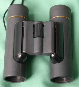 Figure 24 - Rubber-armoured roof prism binoculars, 10x25 Roof prism types are very compact and can easily be carried in a coat pocket. The smaller objective diameter means they are not as suitable for use in low light conditions as ZCF types. One disadvantage is that the hinge plate is sometimes not very rigid and the two tubes can become twisted out of alignment, resulting in 'double vision.' Larger sizes of DCF models however normally have just a single hinge and are more robust. Reverse Porro Prism or MCFEarlier it was described how the Zeiss arrangement of Porro prisms allowed a wider separation between the objective lenses than between the eyepieces. By reversing the prisms from left to right the objectives can be moved to between the line of the eyepieces, making the overall width of the binoculars only slightly more than the inter-ocular separation. See figure 25. This design of binocular is sometimes, confusingly, just called 'Porro prism' but more commonly 'MCF' type. The aperture has to be much less than the eyepiece separation so is normally from 20 to 40mm.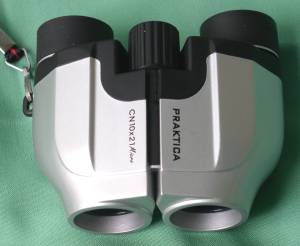 Figure 25 - Reverse Porro prism binoculars, 10x21 MCF types currently seem to be the most popular in the low-end consumer market. The small objective separation means the view is not as obviously '3-D' as with the ZCF design but MCF models are extremely compact and easy to carry about. Having only a single hinge they are less likely to become misaligned than DCF types. Dual-Axis Porro Prism or UCFThis design was introduced by Pentax around 1990. They are similar to MCF in appearance but the objective lenses are a fixed distance apart and the two eyepieces and prism housings swing outwards to adjust the inter-ocular distance. The UCF design is compact and should keep its alignment well.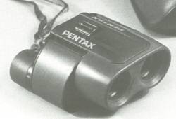 Figure 26 - Pentax UCF Porro prism binoculars, 8x24 | ||||||||||||||||||||||||||||||||||||||||||||||||
| Back to Contents | ||||||||||||||||||||||||||||||||||||||||||||||||
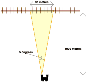
MagnificationIn a binocular specification such as '7x50' or '10x25' the first number is the magnification, i.e. how much larger an object looks through the binoculars than without them. Note that this is a linear measure, that is how many times longer or higher something appears through binoculars. Fixed-magnification binoculars are available with magnifications from about 6 times up to 30 times. Zoom binoculars with magnifications of 100 times or more are advertised. Magnification is of course the main reason for using binoculars, so is the highest possible magnification best? The answer is no, for several reasons. The first problem is with the field of view, that is the amount of the scene in front of you which can be seen at one time through the binoculars. It is inevitable that as the magnification increases the field of view decreases, and in fact doubling the magnification reduces the area visible by a factor of 4. It can be surprisingly difficult to find a target even through 10 times magnification glasses and at 30 times you are likely to find for example that the bird you are trying to see has flown away before you have found it. The effect of magnification on field of view is illustrated in figure 27. The second disadvantage of increasing the magnification is that the same amount of light from the subject is being spread out over a wider area of the retina of your eye, which causes the image to become darker. This may not be too noticeable on a sunny day but on dull days, or in twilight, a very high magnification can make the image too dim to see clearly. The dimming effect of magnification can be counteracted by using larger diameter objective lenses (at the cost of the binoculars being bulkier) and a rough rule is that the magnification should not be more than half the objective lens diameter in millimetres. The most serious problem with high magnifications however is image shake. It is not possible for anyone to hold their hands perfectly still; there is always a slight trembling due to muscle twitches. When holding binoculars up to your eyes this trembling is transferred to the binoculars and increased by their magnification. The result is that the image shakes about and it is difficult to see fine details. So long as the magnification is fairly low the eye can cope with this shaking but once the magnification exceeds about 10 or 12 times it will be impossible to hold the binoculars still enough to see all the detail theoretically revealed, and you would actually see more with a lower magnification. The only way to sensibly use more than 12 times magnifying power is to steady the binoculars in some way. Just resting the ends of the objective lens tubes on the top of a wall or fence can make a huge difference, and 20x then becomes usable. Of course there is not likely to be a handy wall just where you want to view the scenery, and the best way to use high power binoculars is to attach them to a camera tripod. A few binoculars have a tripod bush built into them and ZCF types can often have a simple clamp attached to the central hinge, as in figure 28. Some binoculars however have no provision for attaching them to a tripod, and in any case unless they are being used at a fixed location it is hardly convenient to have to carry a tripod around. In summary then, if the binoculars are going to be carried about and hand-held then it is best to avoid magnifications much over 10x. | ||||||||||||||||||||||||||||||||||||||||||||||||
| Back to Contents | ||||||||||||||||||||||||||||||||||||||||||||||||
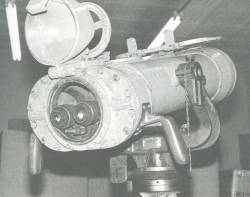
Objective SizeThe second number in the binocular specification '7x50' is the diameter of the objective lenses in millimetres. A larger diameter means the binoculars collect more light from the scene and provide a brighter image. Except in the case of Galilean opera glasses, bigger lenses do not give a wider view. General-purpose binoculars have apertures between 20mm and 50mm, whilst those intended for low-light conditions or astronomy can be 100mm or more. Larger objective lenses will normally give better images but of course make the binoculars heavier and bulkier. Figure 29 shows a pair of 120mm aperture 'battleship' binoculars, which would provide excellent views at dusk or even at night if there is moonlight, but they are clearly not portable. For daylight use 25 to 40mm aperture is a reasonable compromise between brightness and portability. For astronomy 50mm is about the minimum useful aperture and 80mm or 100mm models will give considerably better views. Remember though that binoculars of this size will weigh about 4 kilograms and some kind of tripod support is essential. | ||||||||||||||||||||||||||||||||||||||||||||||||
| Back to Contents | ||||||||||||||||||||||||||||||||||||||||||||||||
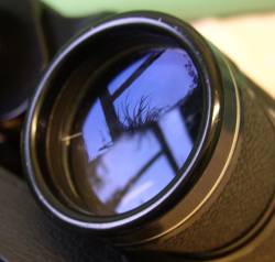
Exit Pupil and Eye ReliefIf you point a pair of binoculars at a bright sky and look at the eyepiece, rather than into it, you will see a bright disc of light near the centre which appears to be floating above the lens. See figure 30. This is the exit pupil and represents the cone of light forming the image. The distance the exit pupil is behind the eyepiece lens is the eye relief and this is the best place to position the pupil of your eye when looking through the binoculars, to obtain the widest field of view and brightest image. If the eye relief is too short then it may not be possible to bring the eye close enough to the eyepiece while wearing glasses. The diameter of the exit pupil can be calculated as the objective diameter divided by the magnification, and the larger the exit pupil the brighter the image seen through the binoculars, and the more suitable they are for use in dim lighting. The limit though is that there is no point in having an exit pupil larger than the pupil of your eye, or some of the light forming the image will be wasted. In bright daylight the eye's pupil contracts to 2 to 3mm diameter, so 10x25 binoculars with an exit pupil of 2.5mm give adequate brightness. If you are young and have been in a dark location for some time then your pupil can dilate up to 7mm diameter, and in that case a pair of 10x70 binoculars would provide a much brighter image. Most of the time your pupils will not be fully dilated even at night because of ambient lighting and age, and there is little advantage in having an exit pupil above 5mm. Thus 10x50 binoculars would be as bright as 10x70s. The eye behaves like a camera, and just like a camera it has an f-ratio determined as the focal length of the lens divided by its aperture. An average eye has a focal length of about 17mm and if your pupil is dilated to 5mm diameter, the eye's f-number is 17/5 or f 3.4. The consequence is that if binoculars are being used in dark conditions, such as for astronomy, there is a maximum worthwhile objective lens size for a given magnification, or alternatively a minimum magnification for a particular objective diameter. Typical binocular specifications suitable for low-light use would be 10x50, 15x80, 20x100. A peculiarity of Galilean optics is that the exit pupil is between the eyepiece and objective, where it is impossible to place your eye, and thus Galilean telescopes give a dimmer view at a given magnification/objective diameter combination than other types. | ||||||||||||||||||||||||||||||||||||||||||||||||
| Back to Contents | ||||||||||||||||||||||||||||||||||||||||||||||||
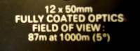
Field of ViewThere are two kinds of field of view, real field and apparent field. The apparent field of view of binoculars is how wide the circular view seen through the binoculars appears to be to the eye. The apparent field is always equal to the real field in degrees multiplied by the magnification. Some typical magnifications and real and apparent fields are:
The binoculars in this table are arranged in order of increasing magnification and it can be seen that in general the real field of view decreases as the magnification goes up, whereas the apparent field is fairly constant at about 60 degrees. To achieve a field of view more than 60 degrees or so requires more complicated and expensive eyepieces (usually Erfle type) and larger prisms, so only tends to be available on more expensive models. Even so 75 to 80 degrees of apparent field is the absolute limit without distorting the image. 'Wide Field' binoculars are available with a wider than average field of view for their magnification, which is an advantage in allowing more of the scene to be visible, but they will usually be more expensive than 'standard field' models and the image may become out of focus towards the edges. Zoom binoculars often have a narrower field of view at a given magnification than fixed magnification binoculars have. | ||||||||||||||||||||||||||||||||||||||||||||||||
| Back to Contents | ||||||||||||||||||||||||||||||||||||||||||||||||
Focussing MethodThe vast majority of binoculars have centre focus, whereby turning a central wheel moves both eyepieces. The right-hand eyepiece can also be screwed in and out a small distance (called 'dioptre adjustment') to allow for any slight difference in focussing between left and right eyes. It also means most people who wear glasses do not need them when using binoculars. A few models have 'instafocus', which allows the full focussing range to be covered by pressing a lever or by only about half a turn of a wheel, rather than several turns. This is most likely to be an advantage for something like bird watching where you are trying to follow a moving target, but otherwise may make it difficult to obtain precise focus. Military specification binoculars traditionally have eyepieces which focus individually by screwing in with an internal thread. Although this is slower than centre-focus there is no exposed threaded rod to collect dirt and it is easier to seal the optics against dust and moisture. Occasionally 'fixed-focus' binoculars are advertised, which in effect have the focus permanently set to infinity. This is only feasible at low magnifications, up to about 6x, and even then anything closer than about 10 metres will be blurred. Also if you normally wear glasses you will probably still need them when using fixed-focus binoculars. Minolta have even produced models with autofocus, but I suspect it will suffer from the same problem as autofocus in cameras, i.e. a tendency to focus on the distant background when you are trying to observe something close-to, or vice-versa. | ||||||||||||||||||||||||||||||||||||||||||||||||
| Back to Contents | ||||||||||||||||||||||||||||||||||||||||||||||||
ResolutionThe laws of physics set a limit on how much detail any optical system can resolve, even if it is perfectly made. Resolution is normally quoted in terms of the minimum angular separation of two lines which can just be seen as distinct rather than merging into one. The larger the objective lens of binoculars or a telescope the finer the resolution, and specifically the Dawes Limit says that the resolving power in arcseconds is 116 divided by the aperture in millimetres, where an arcsecond is 1/3600 of a degree. This means there is also a maximum useful magnification for a given aperture of objective lens, such that the resolving power of the lens multiplied by the magnification equals the resolving power of the human eye. Exactly what this maximum magnification is depends on the user's eyesight but typically it equates to 2x magnification for each millimetre of aperture. The maximum magnification for 50mm lenses is thus 100 times. Exceeding this maximum magnification just makes the image dimmer and does not reveal any more detail. For binoculars the magnification is generally well below the theoretical maximum, though I have seen a pair of zoom binoculars advertised with up to 100 times magnification but only 30mm objectives. Any more than 50 to 60 times is wasted with 30mm lenses, even if they could be held steady. | ||||||||||||||||||||||||||||||||||||||||||||||||
| Back to Contents | ||||||||||||||||||||||||||||||||||||||||||||||||
Quality of BinocularsThe price of binoculars can vary from about £20 up to several hundred pounds, even for apparently similar specifications, so what are the advantages of the more expensive models?
| ||||||||||||||||||||||||||||||||||||||||||||||||
| Back to Contents | ||||||||||||||||||||||||||||||||||||||||||||||||
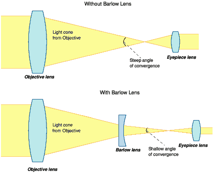
Zoom BinocularsAs mentioned in the section on Keplerian optics, the magnification of any telescope or pair of binoculars is equal to the focal length of the objective lens divided by the focal length of the eyepiece lens. Increasing the magnification normally means either using a longer focal length objective (making the instrument itself longer) or a shorter focal length eyepiece which is difficult to make and will have short eye relief. However, all that is really required is to make the converging cone of light from the objective lens converge at a shallower angle, and this has the same effect as increasing the focal length of the lens. This can be achieved by placing a weakly diverging, concave, lens before the eyepiece, as shown in figure 32. Such a lens is called a Barlow Lens after its inventor Peter Barlow (1776 - 1862) and is often used with astronomical telescopes. The amount of extra magnification produced by a Barlow lens depends on its precise position between the objective and eyepiece, and in zoom binoculars there is a mechanism to slide the lens backwards and forwards simultaneously in both eyepiece barrels, thus altering the magnification. Usually the zoom is controlled by a lever near one eyepiece, and the optics are designed so that there is no need to refocus while zooming. In theory a zoom function should be very useful; you could use a low magnification (with a wide field of view) to find an object then zoom in to see it more clearly. In practice there are several disadvantages:
| ||||||||||||||||||||||||||||||||||||||||||||||||
| Back to Contents | ||||||||||||||||||||||||||||||||||||||||||||||||
CasesBinoculars are invariably supplied with some sort of case. For compact roof prism or MCF types which will be carried in a coat pocket a soft vinyl or fabric case is adequate. For larger ZCF types that will be carried by a strap over the shoulder a well fitting rigid case is essential. The binoculars are bound to get bashed against a post sooner or later while climbing over a stile and a soft case will not protect them. Plastic lens caps are often provided but unless they are the type which is permanently attached to the body of the binoculars they tend to get lost. Lens caps should not be necessary if the binoculars are put back in their case when not being used. | ||||||||||||||||||||||||||||||||||||||||||||||||
| Back to Contents | ||||||||||||||||||||||||||||||||||||||||||||||||
Choosing BinocularsThe best binoculars to choose depends on their intended use, and a compromise has to be reached between such factors as image brightness, magnification, weight, quality and price. Suggestions for specific purposes are given below but some general comments are:
| ||||||||||||||||||||||||||||||||||||||||||||||||
| Back to Contents | ||||||||||||||||||||||||||||||||||||||||||||||||
Binoculars for Bird WatchingBird watching binoculars will nearly always be hand held and are likely to be carried for a long time. The largest practical objective size is 50mm, but 30 to 40mm sizes may well be easier to hold. Magnification should be no more than about 10x, both to make them easier to hold steady and to ensure a reasonably large exit pupil for use at twilight. Typical specifications are 8x30, 7x35, 8x40, 10x50. The binoculars need not be particularly compact since they are being carried for a purpose so ZCF or large roof prism binoculars are suitable, as shown in figure 33. While bird watching the binoculars are likely to be carried out of their case for long periods so it is worthwhile paying extra for rubber armoured and rain proof models, and make sure the neck strap is comfortable. The ability to focus on close objects is essential so look for a minimum focussing distance of around 3 metres. Fast focus designs are useful but avoid fixed focus types. | ||||||||||||||||||||||||||||||||||||||||||||||||
| Back to Contents | ||||||||||||||||||||||||||||||||||||||||||||||||
Binoculars for AstronomyAmateur astronomers often use binoculars instead of a telescope because of their wide field of view, lack of setting up, and comfort in using both eyes. It is a fact that you can see slightly fainter stars using both eyes than with either eye on its own. Most astronomical objects are faint and of low contrast and thus image brightness is a key consideration. If the binoculars are to be hand-held then 50 to 60mm objectives are the usual choice - apertures of less than 50mm do not really collect enough light for astronomy. There are currently some lightweight 15x70 models sold under various brand names, including Celestron, which are still hand-holdable and have received good reviews. Remember to budget for the cost of a specialised tripod since a standard camera tripod will probably not be able to cope with so much weight tilted upwards at a steep angle, and never seems to be tall enough to stand underneath. A tripod for astro-binoculars needs to be taller than you are so that you can look up into the eyepieces without bending your legs, and the tilt axis needs to be firm enough to hold the binoculars in place even when pointing upwards at a steep angle. A suitable tripod is likely to cost upwards of £80. As for magnification, aim for an exit pupil around 4 to 5mm. That means typical specifications will be 10x50, 15x70, 20x80 and 25x100. Higher magnifications are available but are of limited value in astronomy. Finding the object of interest in the night sky can be difficult enough even with a wide field of view, and high magnification reduces the field. Binoculars are not suitable for detailed viewing of the Moon or planets and for this purpose a telescope would be better than high-power binoculars. Fully coated or preferably multicoated optics are a must for astronomy, to increase the contrast of low surface brightness galaxies and to avoid internal reflections looking like extra stars. It is very difficult to look through a pair of binoculars pointing close to the zenith, and if they are mounted on a tripod anything more than about 50 to 60 degrees elevation is awkward because you need to tilt your head back at an uncomfortable angle, and the tripod itself gets in the way. | ||||||||||||||||||||||||||||||||||||||||||||||||
| Back to Contents | ||||||||||||||||||||||||||||||||||||||||||||||||
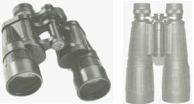
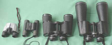
Binoculars for HikingIf the binoculars are to be carried around with you just in case you need them, then you will not want the weight and bulk of large aperture ZCF models. The compact DCF and MCF types are likely to be more suitable. To keep the overall size down the aperture will be in the 20 to 30mm range, and because you will not have a tripod the magnification should be no more than 12x. As a guide, figure 35 shows the relative sizes of various apertures and styles of binoculars. | ||||||||||||||||||||||||||||||||||||||||||||||||
| Back to Contents | ||||||||||||||||||||||||||||||||||||||||||||||||
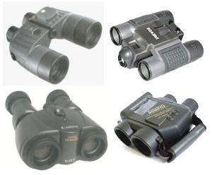
Specialised BinocularsA number of models are available with extra functions. These include: Fully waterproof binoculars are intended for use in boats. Although most binoculars will stand light rain or splashes, if water soaks into them it can damage the cement holding the lens elements together and corrode focussing mechanisms. Water proof models are completely sealed against water and often designed so they will float if dropped into the sea. Sometimes a compass is built in. They are usually filled with dry nitrogen rather than air to prevent internal fogging of the lenses, and have a large exit pupil for optimum image brightness in dark conditions. Binoculars with a built-in camera are another combination. Recent designs are likely to have a digital camera whereas older ones used film.
As has been stated several times, the main factor limiting the magnification of binoculars is the inability to hold them steady by hand, but in recent years image stabilised models have appeared which can cure this problem. Some have a system of gyroscopes to damp out vibration while others use prisms which can tilt slightly so that the image in the eyepiece remains fixed despite small movements of the binocular body. Both types need battery power and are larger and somewhat heavier than standard binoculars but offer vastly clearer viewing when hand held. At the moment image stabilised binoculars are expensive at £250 to £1000 even for modest apertures and magnifications, but the price is likely to drop in coming years and they should become more popular. They may even make the ridiculously high magnifications sometimes offered in zoom binoculars usable. Since all the specialised binoculars are more expensive and usually heavier than simpler types, consider whether you really need their extra features. | ||||||||||||||||||||||||||||||||||||||||||||||||
| Back to Contents | ||||||||||||||||||||||||||||||||||||||||||||||||
Using BinocularsA few notes on how to use binoculars are perhaps worthwhile. The first step is to adjust the interpupillary or interocular distance, i.e. the separation between the two eyepieces. Fold the binoculars inwards to their closest distance then look through them and slowly open them out until both eyes can see the full field of view, which should appear as a circle. Note the setting on the scale on the central hinge if there is one (marked in millimetres), so that the binoculars can easily be returned to the correct separation for your eyes if they are altered. Next, assuming they are centre focus type, the right eyepiece dioptre needs to be set. Look through the binoculars at a distant object, but not through a window. Close your right eye and adjust the focus with the central wheel until the view through your left eye is properly focussed. Now open your right eye, close your left and rotate the right eyepiece until the view through your right eye is focussed, but without altering the centre focus setting. When you have done this the view with both eyes open should be accurately in focus. Again note the setting of the dioptre adjustment, which is usually marked something like 3 2 1 + 0 - 1 2 3. To find a target through binoculars, look directly at it without binoculars then bring them up to your eyes while keeping your head still, and you should find it is in your field of view. MaintenanceBinoculars should need little in the way of maintenance but note:
| ||||||||||||||||||||||||||||||||||||||||||||||||
| Back to Contents | ||||||||||||||||||||||||||||||||||||||||||||||||
Testing BinocularsSome points to check for on a pair of binoculars, particularly if considering a secondhand pair, are:
 Figure 37 - The visual appearance of vertical misalignment. | ||||||||||||||||||||||||||||||||||||||||||||||||
| Back to Contents |
|
Brief BiographyGalileo Galilei was born in Pisa in 1564 and in 1589 became professor of mathematics at the university there. In 1592 he moved to Padua where he worked until 1610, when he was appointed chief mathematician to the grand duke of Tuscany, Ferdinand II. Many of Galileo's theories were counter to accepted biblical teachings and he made many enemies. In 1616 he was compelled by the Roman Inquisition not to contradict Scripture and in 1635 he was tried for heresy, forced to declare that the Earth does not revolve around the Sun, and put under house arrest for his last years. He died in 1642. |
| Back to Contents |
Fields of StudyGalileo Galilei was one of the first to use what is now known as the scientific method, which meant using observations and experiments to deduce the laws of nature, rather than relying on received wisdom and religious dogma. Some of his fields of study were:
|
| Back to Contents |
Crown GlassNormal window glass is made by melting together a mixture of silica (from sand), sodium carbonate and calcium carbonate (limestone), plus small amounts of other metal compounds. Carbon dioxide gas is released as the sodium carbonate and calcium carbonate are converted to their oxides, known as soda and lime respectively. Time has to be allowed for the gas bubbles to escape from the molten glass or they will cause defects in the finished glass. The final product is a complicated silicate and a typical composition is 73% silica, 14% soda, 9% lime, 3.7% magnesium oxide, 0.3% aluminium oxide. The old-fashioned way to make flat panes of glass was to take a blob of molten glass and blow it into a sphere. This was then cut off the blowpipe and transferred to a rod which was spun quickly, causing the sphere to open out into a flat disc of glass. After cooling this disc was cut into separate panes. Where the rod had been attached to the centre of the disc it left a thicker area of concentric rings, forming the distinctive 'bullseye' pattern often seen in old small windows. The bullseye was sometimes called a 'crown', hence the glass became known as crown glass. | ||||||||||
| Back to Contents | ||||||||||
Flint GlassThe typical composition of flint glass is 57% silica, 31% lead oxide, 12% potassium oxide. Originally crushed flint (a form of microcrystalline quartz) was used as the source of silica, which is how flint glass got its name. Flint glass is denser and has a higher refractive index than crown glass. Typical refractive index values are 1.48 - 1.61 for crown glass and 1.53 - 1.78 for flint glass. | ||||||||||
| Back to Contents | ||||||||||
Other GlassesOther types of glass in use include:
| ||||||||||
| Back to Contents | ||||||||||
Refractive IndexLight travels more slowly through a transparent substance (glass, plastic, water, rock crystal etc.) than it does through a vacuum. The ratio of the speed of light in a vacuum to the speed of light in a particular substance is called the refractive index of that substance. Some example values are:
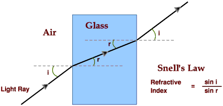
One consequence of refractive index is that when a ray of light passes from air (which with a refractive index of 1.0003 is almost a vacuum) into glass at an angle to the surface, the direction of the ray is bent to a steeper angle; it is said to be refracted. As the ray passes from glass back into air it is refracted again in the opposite direction, to a shallower angle. This leads to an alternative definition of refractive index: | ||||||||||
| Back to Contents | ||||||||||
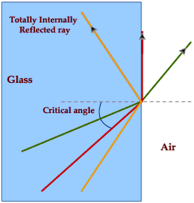
Total Internal ReflectionAs a ray of light passes from glass into air it is refracted so that it makes a shallower angle with the surface of the glass. If it approaches the surface at a sufficiently shallow angle, called the critical angle, it will emerge parallel to the surface of the glass. At shallower angles still it does not leave the glass at all but is reflected back inside, so that the glass surface acts as a mirror. The critical angle, where by convention all angles are measured from a line at right angles to the surface, can be calculated as | ||||||||||
| Back to Contents |
|
|