| In 1937 Pennsylvania Railroad had electrified it's territory from Washington DC to New York Pennsylvania Station. Not until recently have the tools be available to find potential system failures and to prevent downtime by repairing breaks before they happen. One of these tools is infrared imaging. |
| Amtrak set out to test specific abilities of infrared video imaging to be used by it's ET (Electric Traction) Department and also be integrated into it's state of the art asset management system. John Chance Land Surveys was retained to gather infrared image videos from a rail mounted mobile platform. Since IR camers cannot see through glass, outside mounted cameras would have to be used. The easiest to obtain was Amtrak's 10001 "The Beech Grove" executive business car. Simply put, it was the only thing we had with a back porch. |
| One important thing when maintaining a property a few hundred feet wide and hundreds of miles long... Where am I? The answer is provided by Differential Global Positioning Satellite equipment. The "differential" makes it extremely accurate, to the point of defining a point by longitude, latitude, and elevation within a coffee cup. For this exercise however we only required accuracy within a meter, or 3 feet. |
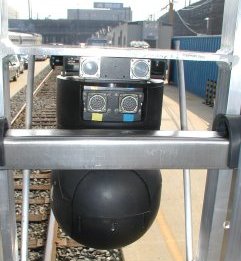
| The masts added to mount the tandem DGPS antennas also provided handy means of attaching other equipment. the fireman's side antenna mount received a cigar sized color video cam (far left)and one of the two hardmount IR fixed focal length cameras. the engineer's side mast received the other IR fixed camera (far right). One was pointed approx 5� skyward and the other slightly below horizontal for maximum coverage. |

| The IR fixed cameras were mounted in enclosures (cans) designed for mounting on aircraft hard points, or in this instance, the John Chance Survey helicopter. These cans were adapted for this exercise to protect the environmentally succeptible IR cameras from harm. |
| The real "toy" of the day was the FLIR (front looking infra red) camera, a joy stick remote controlled cam. top arrow shows cigar video cam. lower arrows show the FLIR infra red cam (big lens) and visible video camera lens. |
|
| The FLIR ball contains a step zoom capable infrared camera and an infinite zoom visible video camera in one pan/tilt enclosure. Again, this device is designed to mount on the nose of a helicopter. Many police helicopters have an identical or very similar camera mounted at the very nose |

| The FLIR ball allows ET personnel on board to control a portion of the survey and document areas not typically on the survey. As we ride through an area, they can aim the IR camera at wayside power substations and focus on possible "trouble spots". This also allows for a second vantage point to spots found on the fixed cameras. The operator has full control of focus, zoom, intensity, and toggle between IR and visible video, as well as real time full pan and tilt capabilities. |

| The FLIR output went directly to a video recorder and then to a video monitor. the output was WYSIWYG (what you see is what you get). For instance if you toggle from ir to visible video, you see the change on the monitor. Also this is recorded just as you would see it on the vcr. Notice the arrow I put on each image pointing to a car's front tire. The infrared image is bright white because of the heat from the disk brakes on the car. Evidently this car was just recently driven. |

| All control instrumentation was contained in a 19" industrial rack enclosure. The design was for use in aircraft, optomizing space, weight, and ease of use. Other elements needed for this test were added as necessary. #1 in the photo shows the FLIR monitor. #2 and #3 are lcd flatpanel monitors for the two fixed ir cameras. #3 also toggled to view the cigar camera output. #4 shows three 12 volt mini video recorders, similar to ones used in law enforcement and surveillance work. a fourth recorder for the FLIR is under the FLIR monitor. #5 shows the two DGPS receivers in the rack used in conjunction with #7 gyro for dead reckoning navigation. This will allow for video exact synchronization later. #6 is an added display not usually used but allows for monitoring of all inputs. #8 is one of the three power supply units used to supply the typical aircraft 28 volts DC. |
|
|
| The infrared images shown above illustrate the ability to view objects as either white as hot or black as hot. The right arrow on the adjacent image shows a typical hotspot. The left arrow shows a hotspot, but from a light bulb within a wayside signal. |
|
|
| Typical use of such equipment as I said before is aerial surveying. The John Chance helicopter survey team flew our railroad previous to our trainbound experiment. They also used IR imaging and the ultra-accurate DGPS positioning system. Reduction of the data typically is handled on a setup similar to the one shown. The screen image shows the downward ir image(#1), forward ir image(#2), forward visible video image(#3), and the digital gps map trace of that particular flight with the location shown in the circle(#4). The operator need only click on a spot on the line and the synchronized video recorders fast forward to that spot. |
| All in all the test seemed, at least preliminarily, a wild success. Post processing of the data will surely tell us more, but the boys from "loos-yana" helped us gain a valuable tool in our struggle toward absolute cost effective maintenance and zero plant downtime |