Computational
Fluid Dynamics
And
Particle Tracking
In
Central Human Airways
|
Computational
Fluid Dynamics |
|
Research Summary
The human central airways open a direct path to gas exchange regions within the lungs. Despite the fact that airways function to filter out all matter other than gases, it is a good means of drug transport. The drug delivery through the airways requires the knowledge of the flow dynamics within it and that of the particles within the flow domain.
Main objectives of the research
1. Validate the CFD
results of the three-dimensional flow of a single bifurcation of human airways
2. Track particles within the flow domain
3. Investigate the pressure flow relationships in the airways, especially in the
upper airways
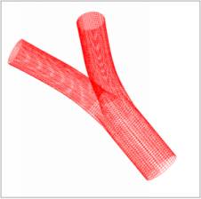
Three-dimensional geometry
The three dimensional geometry parameters used in this research was outlined by Horsefield et al (1971), and they represents a bifurcation lower down the airways. Initially the flow field generated is not expected to represent physiologically realistic flow, but more of flow in an idealized bifurcation. The parent tube cross section is circular before a flow divider where the cross sections are transformed from circular to elliptical to two separate circular daughter tube cross-sections. Hence at the end of the flow divider, in a typical bifurcation two daughter tubes are formed. The daughter tubes usually curve outwards from the bifurcation and then straightens*. The overall geometry chosen for simulation is symmetrical about the parent tube center line.
Two-dimensional geometry
Due to the complexity of the three-dimension geometry and difficult in developing particle tracking code, initially, a two-dimensional double bifurcation model was chosen, which meant to represent the 5th to 7th generation of the human airways.
The outlet boundary conditions of zero relative pressure were chose to allow no forcing on the incoming flow. It was apparent that zero relative pressure does not give desired flow features due to the skewness in the axial flow rate towards the right of the second bifurcation. The two dimensional model also gave separation regions along the outer walls and their size increased along the axial direction with increasing Reynolds number. The branch angle in both bifurcations was 70 degrees. The results are qualitatively validated with those presented by Wilquem et al [2].
CFD Process
The three-dimensional and the two-dimensional model was created and meshed using Fluent pre-processor (Gambit). A multi-block structured mesh was generated. Matlab was used to solve some equations that described the bifurcation geometry and to generate the coordinate points of curves describing the outer geometry. CFX4 solver was also run for the same geometry and boundary conditions for comparison. Some results from such runs were related to the literature and they are in good agreement.
Matlab was extensively used for analysis and for visualisation, and Tecplot for visualization and to produce quality plots.
In house CFD solver called ELMORE was run in parallel (which uses MPI as parallel communication routine) to test its ability to handle multi-block arrangements in three-dimensions. When ELMORE was used it was possible to carryout real-time visualisation using pV3, which uses PVM (Parallel Virtual machine) as communication routines.
Some results from the first year of research are shown below. In all cases, apart from the two-dimensional case, the flow Reynolds number is 1000. Please click on the images to enlarge.
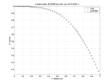
Axial velocity profiles in the bifurcation plane at a position before the flow divider were plotted in figure 1.1 using the data from CFX4 and ELMORE. The graph is symmetrical about the global center line and axes are non-dimensionalized. It can be seen that developed flow entering the bifurcation.
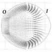
Cross section of the daughter tube in three-dimensional geometry is shown in figure 1.2. The axial flow contour lines at the entrance to the daughter tube can be seen. 'O' refer to outside of the bend and 'I' refer to inside of the bend of a daughter tube.
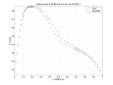
Axial velocity profiles in the bifurcation plane just after the bend but before the straightening in the daughter tube was plotted in figure 1.3. The x-axis and y-axis are non-dimensionalized with respect to daughter tube diameter and mean inlet velocity respectively. It shows skewed axial velocity profile on the daughter tube due to the centrifugal force of the bend acting on the flow field and the formation of a boundary layer at the entrance to the daughter tube. ELMORE and CFX data shows qualitative and quantitative likenesses.
A vector plot (produced in Matlab as quiver plot) showing the secondary flow vectors just after the bend but before the straightening in the daughter tube is shown in figure 1.4.
Axial flow further down the daughter tube is shown in figure 1.5. Axial velocities have been distorted by the action of a pressure gradient produced by the centrifugal force.
Two-dimensional double bifurcation geometry with flow Reynolds number (based on the diameter of the parent tube) equal to 400 is shown in figure 1.6. The outlet boundary conditions are zero relative pressure. From this basic result it is apparent that in the real airways the pressures at the outlets of the daughter tubes must vary from one daughter tube to another, and outlet pressures for both daughter tubes with a branch may not be equal in order to maintain certain amount of flow rate on the outer most branches, away from the central Trachea.Particle tracking
The particle equation of motion given by Maxey and Riley [3] is considered for tracking particles. Their equation was simplified considering the characteristic motion of an aerosol particle of diameter 1-10µm in laminar flow conditions. It is hoped that particle deposition results from literature could be used to validate particle tracks and their respective end points. The current particle equation of motion is only one-way coupling (fluid properties does not get altered due to the presence of the particle). In the future perhaps two-way coupling in particle equation of motion may be introduced.
Pressure boundary conditions
Amongst doing CFD runs and particle tracking I am also reviewing how the airflow is distributed within the airways and investigating the pressure-flow relations that has been proposed by other researches. I hope to gain a fuller understanding of the realistic flow conditions within the airways and how they could be modelled in CFD. It is the realistic outlet pressure boundary conditions that would provide a realistic flow fields.
References
[1] Horsefield K., Dart G., Olson D. E., Filley G. F., Cumming G., “Models of the human bronchial tree”, Journal of Applied Physiology, Vol. 31, No.2 1971.
[2] Wilquem F., Degrez G., "Numerical Modelling of Steady Inspiratory Airflow Through a Three-Generation Model of the Huamn Central Airways",Journal of Biomechanical Engineering (Transactions of ASME), Vol. 119, Feb., 1997.
[3] Maxey M. R., and Riley J. J., “Equation of motion for a small rigid sphere in a non uniform flow”, Physics of Fluids, 26 (4), April 1983.
Any comments, suggestions or queries please send email, [email protected].


