1) Motor while adjusting resonance. 41W (no load connected)
2) Motor power under load 66W (50 ohm load across ecklin output)
3) Load power measured .69adc x 35.1vrms = 24.22W
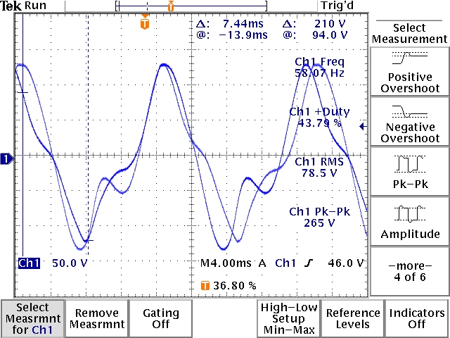
Under load the output waveform transformed into a bipolar squarewave and the scope measurement function (ch1 RMS) read 35.1vrms
The results observed for this test were ok, Nothing OU, but certantly better than the first time i ran it. Improvments made to date included: 1) upgrading the mounting board to steel U channel. 2) finessing the mechanical allignment between the motor and the ecklin,.and 3) Adjusting the rotor gap for minimum clearance....
Future improvments could include 1)reworking the rotor laminants to remove the machined shorts 2) Wrap 8 x 100turn windings to the second stator pole. 3) obtain a variable frequency AC power source to drive the motor at different speeds durring testing.....