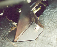
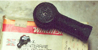
| Feeling like an experienced rack installer, I decided to shim the rack with the factory spacers, to help correct the �bump-steer�. Here you can see the factory spacer still in place. The factory steering rack was modified by adding this spacer on the later cars to improve bump steer. It was initially part of the factory Gr4 and Gr3 race package, later incorporated into the L-model era road cars and later. My �L�, #4580, 11/72, did not have this upgrade, however. |
| Bump Steer is the sensation of the car pulling to one side, when a tire goes over a bump or in a pot hole. At speed this can be very un-nerving to have the steering so affected. Why does it occur ? The angle of the steering rod(s) (from the steering rack to the hub assembly) is not parallel with the A-arm. When the car goes over a bump, and a hub rises, the steering rod connected to it follows in an arc, thus changing the toe-in temporarily. This has the same effect as if the length of the rack rod moves, as when the steering wheel is turned. You notice this effect with harsh bumps as a strong, quick twist of the steering wheel. |
| The bump steer effect is minimized when the steering rack rods are parallel with the upper control arm. The upper control arm should be more or less level when the car is static. The DeTomaso factory created a rack spacer of specific dimensions and installed this below the steering rack mount on either side. The thickness of the spacer determines the height of the rack, and affects the angle of the steering rods. The spacer improves, but does not eliminate the bump steer effect. After installing even just the spacers, the alignment should be verified. Only the toe-in setting should be affected. |
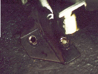
| I now had Mike Drew�s steering rack article in hand, which first appeared in the July 2000 PCNC newsletter. It appeared in a later POCA issue. What I found was that my rack mounted in a slightly different location as the rack in Mike�s story. This is due to either the difference in the size of the shim Mike and I used, or the hand-built nature of our cars. I installed the spacer under the mount, and put the rack support in place, then marked where to drill the new holes. I had to drill the new holes partly over-lapping the existing holes, creating an �8�. The choice was either to over-lap the support, or overlap the chassis hole. |
| Murphy�s Son�s luck was not done yet�for as I lined up the bracket to mark the holes for drilling, the factory spacer fell out. Where could it land causing the most damage ? Well since I was wearing protective glasses, it chose to hit the very edge of my bottom teeth ! Two of my front teeth shattered (vertically), leaving thin, split, triangular front teeth. Lovely ! I looked like a shark, and was as mad as one too. |
 |
 |
| Returning from the dentist ($$$), I examined the tie rod end boots. These boots are packaged in a TRW Federal-Mogul box, with the following part number: 969206. These boots fit horribly ! There is about an 1/8" gap where the base of the boot would attach with the assembly, in the area where the stock boots have that coil/spring ring that fits in the base groove. There is also about an 1/8" gap between the boot and where the shaft goes through it. |
 |
 |
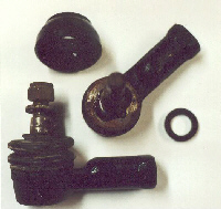
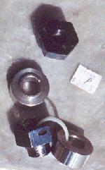
| The pinion seal is seen in the lower right of the image. |
| The tie rod end in the lower left of the image contains the stock boot and spring retainer. The boot at the top is the suspect part. There is no retainer groove, and the hole is too large for the spindle shaft. Setting these aside, I ordered the right boots from Pantera Performance Center of Colorado, (303) 660-9897. Rai assured me that their Lockheed boots fit correctly. While waiting for the parts, I decided to tap the tie rod end for a standard zerk fitting. As you can see in the image, there is a hole in the ball joint cup that will pass grease to the ball. |
 |
| After the hole was drilled, and tapped with a self-clearing 1/4-28 bottom tap with a high helix, which extracts the material as it threads, I installed a 45-degree zerk fitting. I placed two washers under the base, to stand-off the fitting to allow access for the snout of my grease gun. |
 |
| When drilling the hole, be sure to drill thru the plastic cup, so the grease gets to the ball. I added grease with the boot removed, and I noticed the ball became harder to move once the grease was applied. I insured that the grease flowed around the ball. A few days later the boots arrived, and Rai was right. No problems what so ever ! She told me these are the same boots used on the other ball joints too. When I installed the ends on the rack, the ball would turn as I attempted to tighten the nut, so I added more grease and that created enough tension to finish tightening the nut. |
| The rack was the last thing to complete before my car was ready to go to the paint shop, or so I thought�.. But that is another story on replacing the brake master cylinder. |
 |
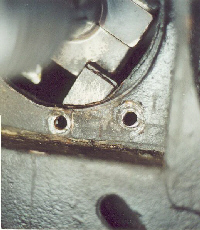
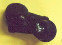
| An alternate design, which does not require the relocation of the rack housing support, is where a pair of parts (In this image one part is black, the other is not) are added to increase the height between the tie rod end, and the lever arm that the tie rod attaches to. So one design lowers the steering rack, where the other design raises the arm to which the tie rod attaches. When I locate an image of this design installed, I'll add it here. Although it may be slightly more work to lower the rack, I prefer this method. |
| Image of installed tie rod spacer |