|
|
|
|
|
|
|
|
|
 |
|
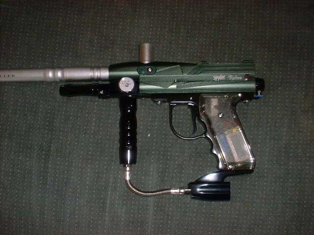
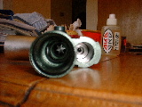
| First step of the rebuild process is to remove the link pin from the bolt, then install the new pin from the kit. This is done by removing the set screw from the side of the bolt. Then pull out the old pin, and slide in the new. Then reinstall the set screw into the side of the bolt. |
|
|
|
|
Click on thumbnails for larger images. |
|
|
|
|
|
|
|
 |
|
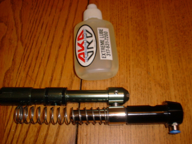
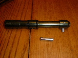
| Next lubricate all the o-rings on the bolt and ram. The slide the ram into the ram sleeve. Then slide the return spring over the ram, and connect the bolt to the ram. |
|
|
|
|
|
|
 |
|
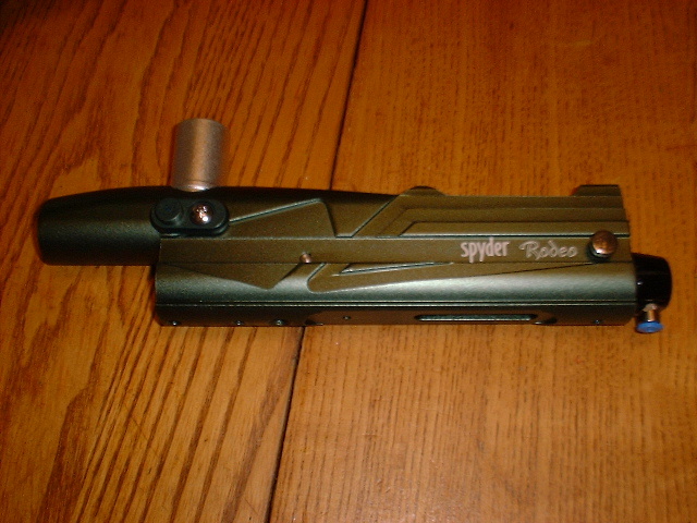
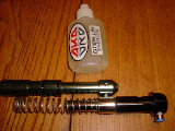
| After the new internals have been assembled, place them into the receiver and secure them in place with the quick strip pin. |
|
|
|
|
|
|
 |
|
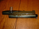
| Now comes the hardest part of the rebuild (and its not very hard). Slide the valve into the front of the receiver, making sure that the big hole in the valve is facing the front of the receiver. Align the hole on the bottom of the valve with the set screw hole, and reinstall the brass set screw. |
|
|
|
|
|
|
 |
|
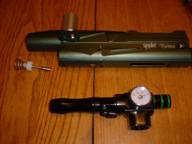
| Now place the valve pin, cupseal and valve spring into the front of the receiver. Make sure the valve pin goes through the valve. |
|
|
|
|
|
|
 |
|
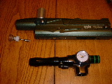
| Then place the verticle asa and low pressure regulator assembly into the front of the receiver. Secure the asa to the receiver using the supplied screw (has some plumbers tape already on it) |
|
|
|
|
|
|
 |
|
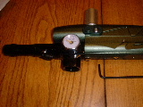
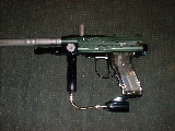
| Now its time to place the grip frame on the receiver using the stock grip frame screws. I had to remove the washers from the screws to in order to securely fasten the frame to the receiver. After the frame is attached, connect your air lines to the low pressure regulator and ram sleeve. |
|
|
|
|
 |
|
|
|
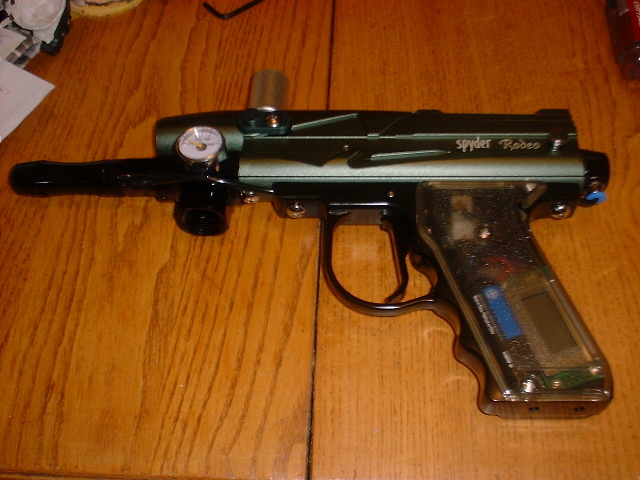
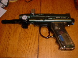
| Finaly attach the new regulator and drop forward to the marker. Screw the regulator into the vertical ASA, then attach the drop forward using the supplied screws. |
|
|
|
|
|
|
[Go back to first page] |
|