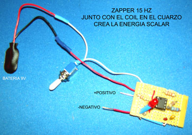
ZAPPER & GENERADOR DE FRECUENCIA PARA CREAR LA ENERGIA SCALAR
...........
What is a zapper?
The zapper is a bio frequency device.
Here you can read what Dr. Hulda Clark says about the zapper: http://www.drclark.net/disease/zapper.htm. The zapper emits a pulse with a frequency of about 30,000 Hz. Dr. Clark makes it clear that it is very important that this pulse is only in the positive range (no negative voltage). Most zappers work on a 9V battery. Most people feel nothing when using a zapper, but some may feel a tingle. The zapper can be used as a medical device in Europe, where it is approved "for use with chronic infections with bacteria, virus, fungus and parasites". In the US, it is not a medical device and can't be used for medical purposes.
Building your Own Zapper
Disclaimer: This circuit is very similar to the one used in Don�s Terminator, but the Terminator contains
other devices & feature not shown here.
This document only refers to the basic square wave generation of
the zapper.
This project will be particularly useful to power a Succor Punch,(Scalar Waves) for example, or for experimentation.
Components have been provided for both the zapper function and the succor punch function.
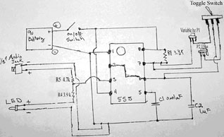
This circuit is based on a 555 timer, officially called NE555. It makes an excellent square wave oscillator,
is readily available and is inexpensive. It is housed in an 8 pin package. It can operate from 4.5 volts to 15
volts.
The frequency is not dependant on the voltage. A 9 Volts battery is a convenient way to power it for
portability. A standard 9v battery will last approximately 9days with this design.
The frequency and duty cycle
(ratio of On and Off time) are
defined by the resistors R1,
R2 and capacitor C2.
When R2 is much larger than
R1 the duty cycle is very
close to 50%, so the On and
Off times are of the same
duration, which is what we
want.
The Capacitor C1 is only used
for stability and the value is
not critical, but it should be
low, in the order of 10 to 47
pico farad (same as 0.01 to
0.047 micro farad)
R4 is used to limit the current flowing into the LED (light emitting Diode) a standard 3 mm red LED light
is used here. A lower resistor value will make the light brighter, but will drain the battery faster. The
minimal value acceptable would be 2.2k
R3 This resistor protect the circuit in case someone short circuits the coins temporarily. It is relatively small
compared with the skin resistance.
R5 : This resistor protects the circuit for short circuits condition. Actually the Succor Punch acts like a short
circuit, (the coil has very low resistance) so this condition can be sustained permanently without damaging
the circuit.
Power Consumption: A number of combinations of R1, R2 and C2 can produce the same frequency, but
the power consumption may not be the same.
The circuit described here will work for around 9 days
nonstop connected to a Succor Punch, with a standard 9v battery.
Longer operating times are obtained with
higher quality batteries. It would last longer as a Zapper mode than as a Succor Punch.
The frequency we are looking for is 15Hz. This mean we
will have fifteen On - Off cycles per second.
One On -
Off cycle will last approximately 66.6 milliseconds.
This square wave can be observed with an oscilloscope.
It cannot be measured with a voltmeter as it changes too
rapidly for it. So the real test of the circuit is visual, by the
blinking rate of the LED light.
If you made an error in the construction, it is possible that the blinking rate is so fast that the light appears
to be On all the time.
Selecting the components: The components are easily found:
C2 1 micro farad, 35 volts tantalum capacitor, the bottom leg is the plus (silver line and
plus sign on that side)
C1 103k, 10P 2A153J (alternative appearances)
The LED light, the longer leg is the plus side
R1 and R2 must be folded to fit on the board. If using 2 resistors, solder then as below
R2 single resistor R2 double resistor On / Off switch
A NE555 device: the dot, on the bottom left of the device (in this image) indicates pin 1. In
some devices, a notch indicates the top. Pin 1 is always at the left of the notch.
A piece of Vero board, or similar electronic project board. They have holes equally
spaced, some have little solder pads on the back. Some have tracks already laid out in
straight lines; you may have to be careful to cut the unwanted tracks in this case.
Some do not have soldering pads, and you use the legs of the components to make the
connections.
A 9v battery connector, they usually come with a
red and black wires attached. The red is the plus side.
You may also want to insert your project in a box and add a switch. The switch would be interrupting the
positive side (red wire) of the battery cable.
To make sure you get the proper values for the resistors, I have attached the color-codes for 10% precision
resistors. Resistor with 1% precision are coded differently, using 1% resistors would be an overkill in this
design.
Component Value Colors
R1 3.3k Orange, Orange, Red
R2 See table below
R3 1k Brown, Black, Red
R4 3.9k Orange, White, Red
R5 4.7k Yellow, Purple, Red
C1 0.01micro farad (or 10 Pico farad)
C2 1 micro farad, 16 or 25 volts
L1 3ml LED
Resistor values are expressed by color bands, plus a band for the tolerance.
Tolerance colors: Gold=5% , silver = 10%. I have not shown the tolerance color here, 10% is fine but
remember the following:
33k with 10% precision means that the real value in reality is between 29.70k and 36.30k.
33k with 5% precision means that the real value in reality is between 31.35k and 34.65k.
So check the table below to see what kind of marging you get. In practice 10% is fine.
Cycle duration = 1 / Frequency, so 1 / 15Hz = 0.066 seconds (66 milli seconds)
Frequency R2 Colors
12.14 56k green, blue, orange
14.10 47k yellow, purple, orange
14.60 39k + 6.2k orange, white, orange + blue, red, red
14.84 39k + 5.6k orange, white, orange + green, blue, red
15.00 39k + 4.7k orange, white, orange + yellow, purple, red < zapper
15.57 39k + 3.9k orange, white, orange + orange, White, red
15.65 39k + 3.3k orange, white, orange + orange, Orange, red
17.00 39k orange, white, orange
19.93 33k orange, orange, orange
24.34 27k red, purple, orange
29.60 22k red, red, orange
30.70 20k + 1.2k red, black, orange + brown, red, red
31.00 20k + 1k red, black, orange + brown, black, red
31.15 20k + 820 ohm red, black, orange + grey, red, brown
31.48 20k + 620 ohm red, black, orange + blue, red, brown
31.56 20k + 560 ohm red, black, orange + green, blue, brown
32.00 20k + 470 ohm red, black, orange + yellow, purple, brown < crystal programming
32.44 20k red, black, orange
Construction: It is a good idea to position all the components properly before starting to solder them.
Position the NE555 at the center of the board first and bend some pins so that it does not fall when you turn
the board over to solder.
Insert R1 and R2, bend the
legs to fit the board and use
the cut out legs as wires to
make other connections.
Make sure the longest leg of
L1 is connected to the Plus
and C2 plus side (marked by
a plus sign on the body) is
connected as indicated,
otherwise the circuit will not
work, or not for long.
L1 should be inserted on the
back of the board if you wish
to insert your project in a
box. It could then show
through a hole in the box.
Before connecting the power,
it is VERY IMPORTANT to
check that all connections are
correct and that the polarity
of the battery is right.
If a wire is missing or the battery polarity incorrect, the NE555 will be dead and the circuit will never work.
If the circuit is fine and works, it will work pretty much for ever. I have some timers still working after 10
years of use, and they are on 24 hours a day.
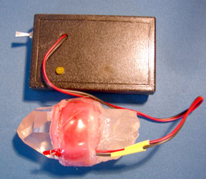
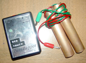
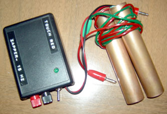
Installing the Circuit in a Box:
You will have to get a small plastic box for your circuit. Drill a hole for the light, drill a hole for the switch
and one for the SP wires.
You can use a small jack connector if you wish to disconnect the SP cable (the
one terminated with the crocodile clips).
You can also add a velcro strip to hold your zapper on you arm or leg.
Depending if you have soldered the LED light on the front of back of the board, install the circuit in the box
so that the light faces the hole.
Use glue to hold in place. A hot glue gun is the handiest way to secure parts
inside the box so they do not move.
18 reading were taken over 9 day. The zapper stopped at the end of the 9th day when battery was at 3.36
volts. It had ran for 214 hours of continuous operation.
Questions and Answers:
Q: is this the same circuit as Dr Clark zapper ?
A: Yes, but the frequency is different, here we use 15hz
Q: Why use 15Hz ?
A: We use 15Hz because it seems to kill parasites very effectively. It also feels good to balanced, healthy
people and boosts our awareness. A theory is that it will be the earth�s resonant frequency in the future.
Q: is this the same circuit as in Don�s Terminator ?
A: Yes, same frequency but the component values may be different. This has no effect on the output. I just
did not want to copy his design. The circuit itself is a well-known electronic circuit freely available.
Q: Will the circuit be damaged if I short-circuit the coins or Sp output?
A: No, the output is protected by resistors to limit the current drain.
Q: Will the NE555 component be damaged if I power it the first time with a faulty wiring?
A: Yes, you will have to replace the NE555, fix the fault and start testing again
Q: Can I make the light brighter?
A: Yes, make resistor R4 smaller. The lowest value acceptable is 2.2k. but the battery will not last as long.
Q: Do I have to use coins?
A: No, you could also use a coil of copper wire like a Loohan coil. Coins made of copper are easy to solder
and glue on a box. There may be health benefits to use copper on the skin. Anything metalic which can be
soldered would do, I guess.
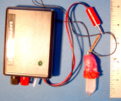
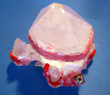
The Succor Punch
http://educate-yourself.org/dc/spindex.shtml
Brief Description
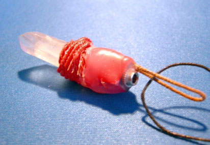
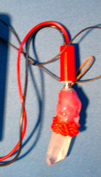
A Succor Punch ("SP") is the name coined for a quartz crystal that has a mobius coil (also called a caduceus coil) wrapped around it in a special knotting configuration
The special knot creates a 'node' which enhances the desired action.
When you pulse a square wave signal from a squarewave signal generator (I call my 15 Hz squarewave generator the SP Pulser -described below) into the mobius coil, it sets up a chaos field which interacts with the crystal to create scalar waves which can then be programmed with your thoughts.
Forces are set in motion both on the third and fourth dimensional levels.
To utilize the SP, you turn it on and hold it over your heart chakra and tell it what you want it to do.
If you are a victim of ELF or microwave Psychotronic torture, you instruct the SP to create a perfect shield against any form of harmful energy that is beamed at you from any dimension, which is intended to cause you harm from any sentient being or thought form directing that harmful energy towards you.
You also program the SP crystal to transmute any negative directed energy that may penetrate your protective shield, into a life-enhancing energy that invigorates and energizes you, rather than harm you. You can also program the SP to beam the energy back to the responsible offending party or parties who are responsible for sending this negative energy to you, the same negative energy, but in an intensified form that the offending parties are defenseless to shield against.
Some like to refer to this game as "Etheric Warfare", but I prefer the less military term of "Etheric Resistance."
Sometimes, for good measure, I'll ask that the offending energy being returned to the sender is increased by 1,000% or more for as long as the clowns are beaming the energy to me.
You can also ask that any black magician, harmful psychic, remote viewer (human or otherwise), or alien entity who is attempting to harm you, be blocked from influencing or causing you psychic (or demonic) attacks.
You command that any alien entity attempting to attach any sort of etheric (4th dimension) life-draining "cord" or "thought implant" using any form of technology or thought forms that are harmful to you be blocked completely and cause you no harm or negative influcence on any dimension of your being or plane of existence.
In other words, you use it as if it's Aladdin's Lamp and you have the world's most powerful Genie at your beck and call (he's also known as your Higher Self).
Dowsing tells me that I can program the medium size crystal for about 35 tasks.
Some crystals can handle more programs, despite their size.
Each crystal is an individual with unique attributes.
Larger crystals can usually handle more programming and do things more powerfully than smaller crystals, but they all work on the same principle.
The crystal can work without the pulsing circuit, but the power factor is much, much lower. It has been reported that negative aliens of the reptilian variety ( Draconian) cannot stand to be in the environment of the SP pulsing circuit and want to exit quickly.
How to wind the single knot mobius coil generally used in "succor punch"
devices
First - Make yourself a "mobius Cable"
to wind the coil from.
While you can wind
a mobius coil from single strands of wire, it
is a lot more potent when you use a cable
made in the manner described here. Take
a 30 to 60 feet of #20-#30 AWG solid core
copper wire (plastic insulated if using #30
lacquer insulated if using #20) and double
it back on itself twice as shown above.
Pull
a little slack out at the ends of the wire, this
will be the leads of the coil when it is
finished. You should leave yourself at
least 2" for leads, and it is a good idea to
give yourself 6" or so, you can always trim the leads to the required length when the coil is finished.
It is much easier to use a drill to twist the wires than doing it by hand. After experimenting with both
CW and CCW coils, we have discovered that either will work. For many, a CCW coil is more
comfortable.
cable end into the drill to twist it, fold the leads back so that they point towards the end of the
cable opposite the end with the leads.
Then wrap a few turns of electrical tape around the wires to
protect them from the drill. Use about 5 or 6 turns of electrical tape. This provides a cushion so that
when you tighten the drill chuck on the wires, it will not scrape off the insulation.
While working with
the coil, be careful not to scrape the insulation off the wires, or the coil will short out and not work.
1. - Starting with the end of the cable which
does not have the leads, make a circle in the
clockwise direction about the size you want your
finished coil to be.
You can wind the coil around
a core (xtal for your SP) or you can wind the coil
by itself if you are using stiffer wire.
2. - When you complete the first wrap, feed the
wire through the center of the circle so it wraps
around itself as shown. Use a little glue (hot melt
or silicone preferable) to hold the wire in place
where it crosses over itself
3. - Continue winding the wire around the
circle halfway.
4. - Opposite the node, cross the wire over
from the top to the bottom as shown.
5. - When you get back to the node, loop the
wire through the center again. It is not
necessary to use glue at each revolution, but it is
generally a good idea to glue the first wrap in
place, that way the circle will stay the same size
as you wind the coil. Otherwise, it will try to
unravel itself.
6. - Continue winding the coil, repeating steps
1 through 5, as shown. When you run out of
cable, use a little glue to hold the end of the cable
in place.
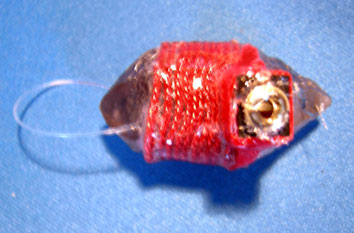
When you are finished, the coil should look
like this when viewed from the side where the
'knot' is.
Just keep wrapping the cable around itself as you go around the circle. Remember to cross
the wire over from the top to the bottom as shown. With a little practice, you will find that the
windings form a pattern, and if you make a mistake it will be obvious as it does not fit the pattern. If
you are winding this coil around a core, it is even simpler, because all you have to do is keep
feeding the end of the wire between the coil and core, once for each revolution.
An alternate to this winding method is to make a large loop of the coil initially and double it
back on itself in a figure-8 pattern until you use up the loop. Just the same as when you put an
elastic band on your hair, except the cable will not stretch so you will have to space the loops out a
bit.
Succor punch Mobius coils-tutorial
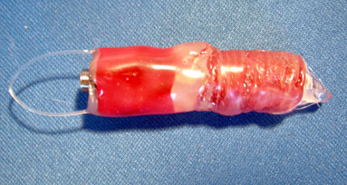
Another alternate to this winding is to stay omit the step of crossing from top to bottom
opposite the knot, and half hitch the cable up the side of the crystal. this technique may be
easier when winding the coil tight against a crystal.
It produces an elongated coil that distributes the
energy along the length of the crystal a bit more.
I recommend using a Quartz, 'Moquis Marble', or Kyanite core for mobius coils, as the energy
generated by a mobius coil (scalar waves) can be biologically disruptive when in its raw state.
This
information is primarily intended for those who wish to use mobius coils as a means of exciting
Quartz crystals or ORgonite, and you are responsible for your own safety.
By making this coil you agree not to hold me responsible for any damages your experiments
may cause to persons or property. Mobius coils generate scalar waves. Scalar waves can interfere
with and/or damage electronics when high voltage is put through them. For the purposes of Orgone
research, low voltages are sufficient to drive mobius coil.
|