07/15/2006
To: General Motors Corporation
From: Olexiy Surgay, and
Vladimir Surgay
1090 S. Towne Ave. #10
Pomona CA 91766
Contact
telephone: (909)-455-7936
e.mail: [email protected]
[email protected]
 Introduction
Here is a Project of the
internal combustion rotary engine.
Advantages of rotary engines
are obvious:
1.
Less metal is needed than the standard combustion engine
2.
A few parts to
build
3.
Greater
power-to-weight ratio
4.
Simple design in
the case
5.
Lower fuel
consumption per Horse Power output
6.
Expected
efficiency is around 70%
Still, existing ideas and
prototypes have severe disadvantages:
1.
Narrow
temperature ranges
2.
Complicated
lubrication system
3.
Sealing problems
We expect to get rid of these
problems by my project.
If you are interested,
lubrication system of the project can be presented to you later. At this time
we only want to introduce concept of the engine work to encourage about
usefulness of the project.
Details of the Design
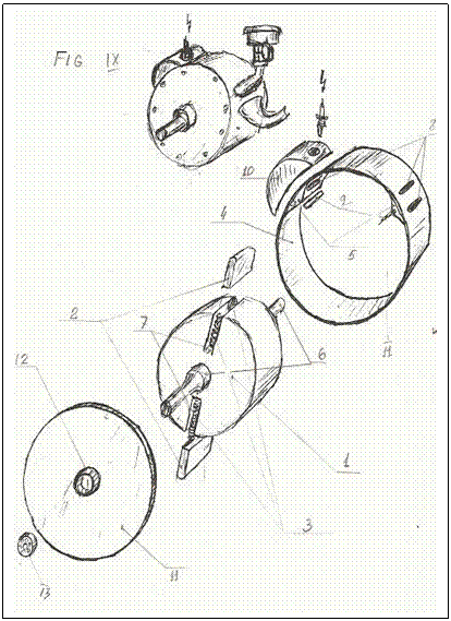
1.
Rotor (Refer to Figure IX)
The
rotor (1) with two slots (7) cut through the rotor in radial direction. It is set
on the shaft (6). Force accepting plates (2) are spring (3) loaded and set into
the slots (7).
2.
The Stator (Refer to Figure IX)
It
is a cylinder with two bumps (5) on the inner surface. These bumps separate the
workforce chamber [(2) Fig. III] from the intake-compression chamber [(1) Fig.
III]. The top portion of the bumps have slots [(1) Fig. I] in which two loaded
springs are inserted to seal the plates [(9) Fig. IX], just like in the rotor
description above. In both sides of the bumps appropriate channels are made.
The function of these channels is:
a.
To intake the
fuel-air mix [(5) Fig. I].
b.
To deliver
compressed fuel mix into the combustion chamber [(10) Fig. IX]. The inlet of
the combustion chamber has a saddle with a ball [(2) Fig. I] carrying the function
of a check valve.
c.
The outlet of the
combustion chamber channel [(3) Fig. I] serves as a deliverer of gases exploded
by a spark to the workforce chamber.
d.
Outlet for
exhaust work force chamber gases [(4) Fig. I].
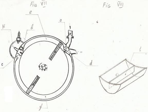
3. Combustion Chamber [(10) Fig. IX]
It
is separately made and is attached to the engine chamber. It has a divider [(1)
Fig. 8] to make two chamber out of one connected by a pathway [(H) Fig.
VII]. Into the combustion chamber a
spark plug is built in.
4. Full Assembly of the Engine
The
rotor and stator are both covered with lids [(11) Fig. IX] with bear (13)
housings [(12) Fig. IX]. A rotor shaft (6) is inserted into the two bearings.
The Concept
of Engine Work
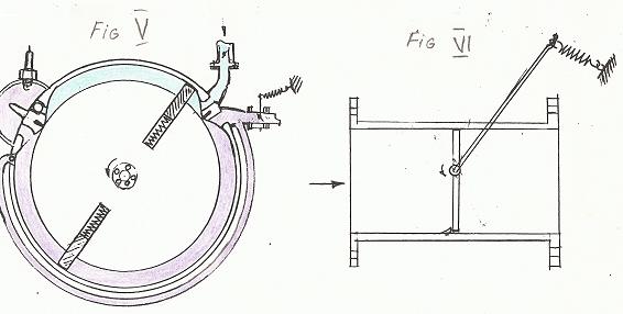
For
engine start refer Fig.V
Rotor spins by engine starter to build-up an initial
pressure in the combustion starter. After this engine start occurs when rotor
is in position shown on Fig.IV. Four strokes take
place by one single rotor turn at any time when engine runs: intake (induction), compression, power (combustion),
and exhaust stroke.
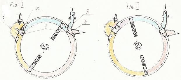
Fig.I
shows the following actions: at lower
department on the left of plate power stroke develops while on the right of the
plate exhaust occurs; at upper department on right side of plate mixture of
fuel and air intake occurs while on left side of the same plate compression
begins.
Fig.II As
soon as pressure before check valve become greater then after the check valve
fuel mix flows into combustion chamber through opening while at opposite side
of the plate fuel mix intake continues.
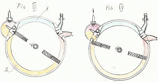
Fig.III Force accepting plate [(2) Fig.IX]
relocates across seal plate [(9) Fig.IX]. Its spring
is fully decompressed. Combustion chamber is partially filled with compressed
fuel mix and ready for ignition and explosion.
Fig.IV
It shows ignition from spark plug while force accepting
plate passed the high pressure delivery channel.
Conclusion
Calculations show that by 1:1 scale of the drawings to
the real engine and rotor with of 10 centimeters. And 3000r/min.power output develops
over 20 horse power by intake volume of 200 cm³ at two full
rotations. To get the same output reciprocating principle engines require
around 600 cm³.
If you are interested in this
project please let me know as soon as possible. If
we don’t get answer from you soon, we are going to send the idea to Mazda
Industries or so.
.
Sincerely
Olexiy Surgay
Vladimir Sugay