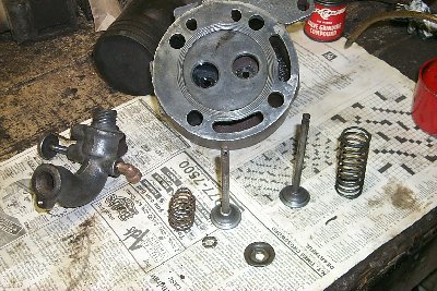
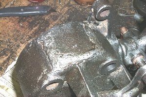
Next was the head. I dissasembled it completely, wire wheeled it, cleaned out the carbon and rust scale from the ports. I wire wheeled the valves, springs, and exhaust keeper. Once wire wheeled, i cleaned everything in gasoline and it looked like the picture below.
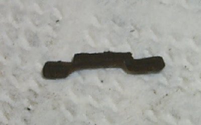
The pivot pin was also very worn where it contacted the head. Again using my torch I brazed the pin where it was worn, then ground off the excess so that it was back to the original diameter. When I reassembled it there was much less play in the linkage and it will work just fine.
I cleaned the outside of the engine around the head area, then decided to clean the water hopper while the head was off. There was a large amount of old grease/oil/dirt at the bottom of the hopper that had built up over the years, and hardened in. Long story short, I ended up putting gasoline in the water hopper while drilling in through the water passages for the head with a long drill bit. In this way I managed to get most of the gunk out, but not all. It was really a mess, and took me at least a couple of hours to get out what I did!
The last thing I needed to disassemble and clean before I started the engine was the crank. Before removing the crank I took a drill bit and marked the cam gear with a slight indentation so I could time it again. I took off the bearing caps and was amazed to see what was used for shims: paper. Different thicknesses of paper (and cardboard) were under each bearing cap. I opted to repleace this paper in one of the bearnings and made shims to fit. The cardboard under one of the caps was almost 3/16" thick! Another interesting thing about these bearings was that had inserts yet under the inserts was poured babbitt. No idea here what someone did and why! After cleaning and relubing the bearings and making the new shims, I reassembled the crank onto the engine, lining up the timing mark I had put on the cam gear.
During the time I was doing these things my new head gasket arrived from Hit&Miss. I reassembled the engine and all that was left before starting it was to clean out the gas tank. I blew air into the filler pipe and lots of rust dust came out of the gas feed hole in the bottom. I decided that I had to take the tank out to really clean it out so I removed the mounting bolts. Upon lifting the engine up and removing the tank I quickly understood why I got so much dust out of it. There was no bottom left! The bottom had turned to rust over the years the engine sat and almost the entire bottom was gone. Time to call Hit&Miss again and order a tank.
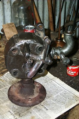
Given this, I opted to use the good old tin can method for a temporary gas tank. This was quickly arranged and I was ready to start it. A couple pulls on the flywheel and it coughed. A couple more pulls and it started! Belched up a bunch of blue smoke and took off! It's always a thrill to hear those first hits and know that all the work was worth it! It ran really good, except that every time it hit I could hear a very loud thump. This, I knew, was caused by the opposite side flywheel being loose on the crank.
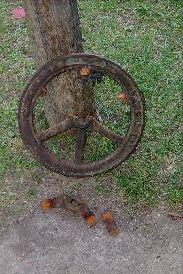
The flywheels on this engine (both sides) had been WELDED to the crankshaft! The flywheel on the side opposite the mag was not even the original flywheel. After getting some advice from Ed at Hit&Miss I decided to pull them both off. First was the non-original one. After using a puller to remove the gear that drives the pump (it was pressed on) I ground off the weld using my die grinder with a small tapered bit. Once I was sure the shaft was free of weld I used the puller to remove the flywheel. It was not all that tight, but the puller just made it easy. I first took out what was left of the key which was very worn. The keyway in the flywheel was badly worn and the keyway in the shaft was worn at the top as well. Once off I inspected the flywheel and found that the hub had a crack in it and the keyway was very worn. As this flywheel did not have a tightening bolt so it was junk. As long as I was removing one flywheel I decided to remove the other even though it was still welded tight to the shaft. After grinding off the weld I started with the puller. Then I broken the puller! This flywheel, although able to rock back and forth on the shaft, would not come off the shaft. After scratching my head for a while, and discovering that this flywheel too had a cracked hub, I decided to cut it off with my acetelene torch. I proceeded to cut three of the spokes, then put a chisel in the hub split and drove it in until the hub split in half. Upon inspection I discovered why the flywheel wouldn't come off. Sometime, obviously in an effort to fix the loose flywheel problem, someone had drilled a 1/4" hole through the hub of the flywheel into the crankshaft, then poured it full of lead or some other material similar.