Wireless
Networking:
Introduction
to Bluetooth and IEEE 802.11 Standards
By: Nishant Soni
([email protected])
Computer Science and
Engineering Department,
Indian Institute of Technology,
Guwahati.
Contents
8.1 Description of Bluetooth Core Protocols
8.1.3. Logical Link Control and Adaptation
Protocol
8.1.4. Service Discovery Protocol
8.2 The Cable Replacement Protocol
8.3 Telephony Control Protocol
8.5 Bluetooth Usage Models and Protocols
9. Connection Establishment in Bluetooth
14.1 The 802.11 Physical Layer
14.2 The 802.11 Data Link Layer
14.2.1 Support for Time-Bounded Data
15.1 Preventing Access to Network Resources
16. Different 802.11 Standards, 802.11a, 802.11b and
802.11g
17. Competing technologies to 802.11
1. Introduction
A wireless network is a flexible data communications system, which uses wireless media such as radio frequency technology to transmit and receive data over the air, minimizing the need for wired connections [1]. Wireless networks are used to augment rather than replace wired networks and are most commonly used to provide last few stages of connectivity between a mobile user and a wired network.
Wireless networks use electromagnetic waves to communicate information from one point to another without relying on any physical connection. Radio waves are often referred to as radio carriers because they simply perform the function of delivering energy to a remote receiver. The data being transmitted is superimposed on the radio carrier so that it can be accurately extracted at the receiving end. Once data is superimposed (modulated) onto the radio carrier, the radio signal occupies more than a single frequency, since the frequency or bit rate of the modulating information adds to the carrier. Multiple radio carriers can exist in the same space at the same time without interfering with each other if the radio waves are transmitted on different radio frequencies. To extract data, a radio receiver tunes in one radio frequency while rejecting all other frequencies. The modulated signal thus received is then demodulated and the data is extracted from the signal.
Wireless networks offer the following productivity, convenience, and cost advantages over traditional wired networks:
- Mobility: provide mobile users with access to real-time information so that they can roam around in the network without getting disconnected from the network. This mobility supports productivity and service opportunities not possible with wired networks.
- Installation speed and simplicity: installing a wireless system can be fast and easy and can eliminate the need to pull cable through walls and ceilings.
- Reach of the network: the network can be extended to places which can not be wired
- More Flexibility: wireless networks offer more flexibility and adapt easily to changes in the configuration of the network.
- Reduced cost of ownership: while the initial investment required for wireless network hardware can be higher than the cost of wired network hardware, overall installation expenses and life-cycle costs can be significantly lower in dynamic environments.
- Scalability: wireless systems can be configured in a variety of topologies to meet the needs of specific applications and installations. Configurations can be easily changed and range from peer-to-peer networks suitable for a small number of users to large infrastructure networks that enable roaming over a broad area.
2. Wireless Usage Scenarios
There are three primary usage scenarios for wireless connectivity [32]:
·
Wireless
Personal Area Networking (WPAN)
·
Wireless
Local Area Networking (WLAN)
·
Wireless
Wide Area Networking (WWAN)
WPAN describes an application of wireless technology that is intended
to address usage scenarios that are inherently personal in nature. The emphasis
is on instant connectivity between devices that manage personal data or which
facilitate data sharing between small groups of individuals. An example might
be synchronizing data between a PDA and a desktop computer. Or another example
might be spontaneous sharing of a document between two or more individuals. The
nature of these types of data sharing scenarios is that they are ad hoc and
often spontaneous. Wireless communication adds value for these types of usage
models by reducing complexity (i.e. eliminates the need for cables).
WLAN on the other is more focused on organizational connectivity not
unlike wire based LAN connections. The intent of WLAN technologies is to
provide members of workgroups access to corporate network resources be it
shared data, shared applications or e-mail but do so in way that does not
inhibit a user’s mobility. The emphasis is on a permanence of the wireless
connection within a defined region like an office building or campus. This
implies that there are wireless access points that define a finite region of
coverage.
Whereas WLAN addresses connectivity within a defined region, WWAN
addresses the need to stay connected while traveling outside this boundary.
Today, cellular technologies enable wireless computer connectivity either via a
cable to a cellular telephone or through PC Card cellular modems. The need
being addressed by WWAN is the need to stay in touch with business critical
communications while traveling.
The following table summarizes each wireless connectivity usage
scenario by a wireless technology.
Table 1 – Wireless Usage
Scenarios by Technology
|
Wireless Standard |
Application Category |
Usage Scenario |
|
Bluetooth |
Wireless Personal Area Networking (WPAN) |
·
I want to instantly connect my notebook
computer to another Bluetooth enabled notebook to transfer a file. ·
I want to collaboratively work on a document
,where meeting participants use notebooks that are wirelessly connected via
Bluetooth. ·
Using a Bluetooth enabled, wireless headset,
I want to listen to a CD playing on my notebook computer while it is in my
briefcase. ·
I often travel to a remote site and want to
walk up to a shared printer, connect and print a document without having to
physically connect using a standard printer cable. ·
I want to connect to the Internet via a
cellular phone without having to take my telephone out of my briefcase |
|
802.11b |
Wireless Local Area Networking (WLAN) |
·
I want to always be connected to my
corporate LAN while moving about in my office building or campus. ·
Usage demands that I have access to
corporate network data at performance levels equivalent to a wire based LAN
connection. |
|
Cellular Technologies (GSM) |
Wireless Wide Area Networking (WWAN) |
·
I want access to e-mail and web resources
while traveling away from the home office. |
Bluetooth and 802.11 are emerging as the preferred technology in the
commercial space for WPAN and WLAN respectively. Higher throughput, longer
range and other characteristics make 802.11 better suited for WLAN than
Bluetooth. The rest of this document gives a basic overview of these two
technologies detailing the basic concepts, the principles of operations, and
some of the reasons behind some of their features.
3. What is Bluetooth
Bluetooth is the name given to a new technology standard using short-range radio links, intended to replace the cable(s) connecting portable and/or fixed electronic devices. The standard defines a uniform structure for a wide range of devices to communicate with each other, with minimal user effort. Its key features are robustness, low complexity, low power and low cost. The technology also offers wireless access to LANs, PSTN, the mobile phone network and the Internet for a host of home appliances and portable handheld interfaces.
4. Motivations for Bluetooth
The immediate need for Bluetooth came from the desire to connect peripherals and devices without cables. The available technology-IrDA OBEX ( Infrared Data Association Object Exchange Protocol ) is based in infrared links that are limited to line of sight connections. Bluetooth is further fueled by the demand for mobile and wireless access to LANs, Internet over mobile and other existing networks, where the backbone is wired but the interface is free to move. This not only makes the network easier to use but also extends its reach. The advantages and rapid proliferation of LANs suggest that setting up personal area networks, that is, connections among devices in the proximity of the user, will have many beneficial uses. Bluetooth could also be used in home networking applications. With increasing numbers of homes having multiple PCs, the need for networks that are simple to install and maintain, is growing. There is also the commercial need to provide "information push" capabilities, which is important for handheld and other such mobile devices and this has been partially incorporated in Bluetooth. Bluetooth's main strength is its ability to simultaneously handle both data and voice transmissions, allowing such innovative solutions as a mobile hands-free headset for voice calls, print to fax capability, and automatically synchronizing PDA, laptop, and cell phone address book applications.
These uses suggest that a technology like Bluetooth is extremely useful and will have a significant effect on the way information is accessed and used.
5. Bluetooth Characteristics
Bluetooth radios operate in the unlicensed ISM band at 2.4 Gigahertz
using 79 channels between 2.402
GHz to 2.480 GHz (23 channels in some countries) [30]. The range for
Bluetooth communication is 0-30 feet (10 meters) with a power consumption of
0dBm (1mW). This distance can be increased to 100 meters by amplifying the
power to 20dBm. The Bluetooth radio system is optimized for mobility.
Bluetooth supports two kinds of links: Asynchronous Connectionless (ACL)
links for data transmission and Synchronous Connection oriented (SCO) links for
audio/voice transmission. The gross Bluetooth data rate is 1 Mbps while the
maximum effective rate on an asymmetric ACL link is 721 Kbps in either
direction and 57.6 Kbps in the return direction. A symmetric ACL link allows
data rates of 432.6 Kbps. Bluetooth also supports up to three 64Kbps SCO
channels per device. These channels are guaranteed bandwidth for transmission.
6. Technology Comparison
Since Bluetooth operates in the unlicensed ISM band that is also used by
other devices such as 802.11 networks, baby monitors, garage door openers,
microwave ovens etc, there is possibility of interference.
Bluetooth uses Frequency Hop Spread Spectrum (FHSS) to avoid any
interference. A Bluetooth channel
is divided into time slots each 625 micro second in length. The devices
hop through these timeslots making 1600 hops per second. This trades bandwidth
efficiency for reliability, integrity and security.
7. Bluetooth Architecture
Bluetooth communication occurs between a master radio and a slave radio.
Bluetooth radios are symmetric in that the same device may operate as a master
and also the slave. Each radio has a 48-bit unique device address (BD_ADDR)
that is fixed.
Two or more radio devices together form ad-hoc networks called piconets.
All units within a piconet share the same channel. Each piconet has one master
device and one or more slaves. There may be up to seven active slaves at a time
within a piconet. Thus, each active device within a piconet is identifiable by
a 3-bit active device address. Inactive slaves in unconnected modes may
continue to reside within the
piconet.
A master is the only one that may initiate a Bluetooth communication
link. However, once a link is established, the slave may request a master/slave
switch to become the master. Slaves are not allowed to talk to each other
directly. All communication occurs within the slave and the master. Slaves
within a piconet must also synchronize their internal clocks and frequency hops
with that of the master. Each piconet uses a different frequency hopping
sequence. Radio devices used Time Division Multiplexing (TDM). A master device
in a piconet transmits on even numbered slots and the slaves may transmit on
odd numbered slots.
Figure 1: Bluetooth Scaternets and Piconets
Multiple piconets with overlapping coverage areas form a scatternet.
Each piconet may have only one
master, but slaves may participate in different piconets on a
time-division multiplex basis. A device may be a master in one piconet and a
slave in another or a slave in more than one piconet.
8. Bluetooth Protocol Stack
The Bluetooth Special Interest Group (SIG) [3] has developed the
Bluetooth Protocol Stack. These specifications allow for developing interactive
services and applications over interoperable radio modules and data
communication protocols. Given below is
an overview of the protocols in the specification.
The main objective of these specifications is to set down the protocols
that must be followed by companies when manufacturing and developing both
software and hardware to interoperate with each other. To achieve this interoperability, matching
applications (e.g., corresponding client and server application) in remote devices
must run over identical protocol stacks.
Different applications may run over different protocol stacks however
they will all have one imperative factor that will allow them to be
interoperable and that will be the use of a common Bluetooth data link and
physical layer. The complete Bluetooth
protocol stack is shown in figure 2. It
may seem that an application must use all protocols shown however not all
applications will make use of all the protocols shown. Instead, applications run over one or more
vertical slices from this protocol stack.
The main principle in mind when developing the Bluetooth Protocol
Architecture has been the maximization and the re-use of existing protocols for
different purposes at the higher layers. The one main advantage is that
existing (legacy) applications can be adapted to work with the Bluetooth
Technology. The Bluetooth Protocol
Architecture also allows for the use of commonly used application protocols on
top of the Bluetooth-Specific protocols.
In simpler terms, this permits new applications to take full advantage
of the capabilities of the Bluetooth technology and for many applications that
are already developed by vendors; they can take immediate advantage of hardware
and software systems, which are also compliant with the Specification.
Figure 2: The Bluetooth Protocol Stack Model
Table 2: The protocols and layers in the Bluetooth protocol stack
Protocol Layer |
Protocols in the stack |
|
Bluetooth Core Protocols |
Baseband [3],LMP [4],L2CAP [5],SDP [6] |
|
Cable Replacement Protocol |
RFCOMM [7] |
|
Telephony Control Protocol |
TCS Binary [8], AT-commands [9], [10], [11] |
|
Adopted Protocols |
PPP [12],UDP/TCP/IP [12],OBEX [13],WAP [14], Vcard [15], vCal [16], IrMC [17],WAE [18] |
In addition to the above protocol layers, the Specification also
defines a Host Controller Interface (HCI).
This provides a command interface to the baseband controller, link
manager, and access to hardware status and control registers.
The Bluetooth Core protocols (plus the Bluetooth radio) are required by
most of Bluetooth devices while the rest of the protocols are used only as
needed. The combination of The Cable
Replacement layer, the Telephony Control layer and the adopted protocol layer
form the application-oriented protocols which enable applications to run over
the Bluetooth Core protocols
8.1
Description of Bluetooth Core Protocols
8.1.1. Baseband
The Baseband and Link Control layer enables the physical RF link between Bluetooth forming a piconet[3]. As the Bluetooth RF system is a Frequency-Hopping-Spread-Spectrum system in simpler terms packets are transmitted in defined time slots on defined frequencies, this synchronizes the transmission hopping frequency and clock of different Bluetooth devices. It provides two different kind of physical links with their corresponding baseband packets, Synchronous Connection-Oriented and Asynchronous Connectionless which can be transmitted in a multiplexing manner on the same RF link. Asynchronous Connectionless (ACL) packets are used for the transmission of data only while Synchronous Connection-Oriented can contain audio only or a combination of audio and data. All audio and data packets can be provided with different levels of FEC or CRC error correction and can be encrypted.
Furthermore, the different
data types, including link management and control messages, are each allocated
a special channel.
Audio
data can be transferred between one or more Bluetooth
devices, making various usage models possible and audio data in SCO packets is
routed directly to and from Baseband and it does not go through L2CAP. Audio
model is relatively simple within Bluetooth; any two Bluetooth devices can send
and receive audio data between each other just by opening an audio link.
8.1.2. Link Manager Protocol
The link manager protocol [4] is responsible for link set-up between
Bluetooth devices. This includes
setting up of security functions like authentication and encryption by
generating, exchanging and checking of link and encryption keys and the control
and negotiation of baseband packet sizes.
Furthermore it
controls the power modes and duty cycles of the Bluetooth radio device, and the
connection states of a Bluetooth unit in a piconet.
8.1.3. Logical Link Control and Adaptation Protocol
The Bluetooth logical
link control and adaptation protocol (L2CAP) [3] adapts upper layer protocols
over the baseband. It can be thought to work in parallel with LMP in difference
that L2CAP provides services to the upper layer when the payload data is never
sent at LMP messages.
L2CAP provides connection-oriented and connectionless data services to the upper layer protocols with protocol multiplexing capability, segmentation and reassembly operation, and group abstractions. L2CAP permits higher-level protocols and applications to transmit and receive L2CAP data packets up to 64 kilobytes in length.
Although the
Baseband protocol provides the SCO and ACL link types,L2CAP is defined only for
ACL links and no support for SCO links is specified in Bluetooth Specification
1.0.
8.1.4. Service Discovery Protocol
Discovery services are crucial part of the Bluetooth framework. These services provide the basis for all the usage models. Using SDP, device information, services and the characteristics of the services can be queried and after that, a connection between two or more Bluetooth devices can be established. SDP
is defined in the
Service Discovery Protocol specification [4].
8.2 The Cable Replacement Protocol
8.2.1 RFCOMM
RFCOMM is a serial
line emulation protocol and is based on ETSI 07.10 ( European Telecommunications
Standardization Institute ) specification. This “cable
replacement” protocol emulates RS-232 control and data signals over Bluetooth
baseband, providing both transport capabilities for upper level services (e.g.
OBEX) that use serial line as transport mechanism. RFCOMM is specified in [7].
8.3
Telephony Control Protocol
Telephony Control protocol - Binary (TCS Binary or TCS BIN) [8], a bit oriented protocol, defines the call control signaling for the establishment of speech and data calls between Bluetooth devices. In addition, it defines mobility management procedures for handling groups of Bluetooth TCS
devices. TCS Binary is specified in the Bluetooth Telephony Control protocol Specification Binary, which is based on the ITU-T Recommendation Q.931 [19], applying the symmetrical provisions as stated in Annex D of Q.931
8.4 Adopted Protocols
8.4.1 PPP
In Bluetooth technologies PPP is designed to run over RFCOMM to accomplish point to point connection. PPP is the IETF Point-to-Point Protocol[12] and PPP-Networking is the means of taking IP packets to/from the PPP layer and placing them onto the LAN. Usage of PPP over Bluetooth is
described in [19].
8.4.2 TCP/UDP/IP
These protocol standards are already defined by the Internet
Engineering Task Force and used commonly in communication across the Internet
[12]. The TCP/IP stacks are used in
numerous devices including printers, handheld computers and mobile handsets the
use of the TCP/IP protocol in the Bluetooth Specification Protocol for the
implementation in Bluetooth devices allows for communication with any other
device connected to the Internet. The
Bluetooth device should be a Bluetooth cellular handset or a data access point
for example is then used as a bridge to the Internet. TCP/IP/PPP is used
for the all Internet Bridge usage scenarios in Bluetooth 1.0 and for OBEX in
future versions [13]. UDP/IP/PPP is also available as transport for WAP [14].
8.4.3 OBEX Protocol
IrOBEX [20] (shortly OBEX) is a session protocol developed by the Infrared Data Association (IrDA) to exchange objects in a simple and spontaneous manner. OBEX, which provides the same basic functionality as HTTP but in a much lighter fashion, uses a client-server model and is independent of the
transport mechanism and transport API, provided it realizes a reliable transport base. Along with the protocol itself, the "grammar" for OBEX conversations between devices, OBEX also provides a model for representing objects and operations. In addition, the OBEX protocol defines a folder-listing object, which is used to browse the contents of folders on remote device. In the first phase, RFCOMM is used as sole transport layer for OBEX [13]. Future implementations are likely to support also TCP/IP as a transport.
Content Formats
vCard [15] and vCalendar [16] are open specifications developed by the versit consortium and now controlled by the Internet Mail Consortium. These specifications define the format of an electronic business card and personal calendar entries and scheduling information, respectively. vCard and
vCalendar do not define any transport mechanism but only the format under which data is transported. By adopting the vCard and vCalendar, the SIG will help further promote the exchange of personal information under these well defined and supported formats. The vCard and vCalendar specifications are
available from the Internet Mail Consortium and are being further developed
by the Internet Engineering Task Force (IETF).
Other content
formats, which are transferred by OBEX in Bluetooth, are vMessage and vNote
[17]. These content formats are also open standards and are used to exchange
messages and notes. They are defined in the IrMC (Infrared Mobile
Communications) specification, which also defines a format for the log files
that are needed when synchronizing data between devices.
8.4.4 WAP
The main advantage of using WAP features in Bluetooth technologies is
to build application gateways, which will mediate between WAP servers and some
other application on the PC. In simpler
terms, this will provide functions like remote control and data fetching from
PC to handset. The idea behind the use of WAP is to reuse the upper software
application developed for the WAP Application Environment Bluetooth Usage
Models and Protocols
8.5 Bluetooth Usage Models and Protocols
In the following text, the highest priority usage models identified by the SIG’s marketing group are briefly introduced. Each usage model is accompanied by a Profile. Profiles define the protocols and protocol features supporting a particular usage model. Bluetooth SIG has specified the profiles for these
usage models. In addition to these profiles, there are four general profiles that are widely utilized by these usage model oriented profiles. These are the generic access profile (GAP) [21], the serial port profile [22], the service discovery application profile (SDAP) [23], and the generic object exchange
profile (GOEP)
[24].
8.5.1 File Transfer
The file transfer usage model (See also the file transfer profile [25]) offers the ability to transfer data objects from one device (e.g., PC, smart-phone, or PDA) to another. Object types include, but are not limited to, .xls, .ppt, .wav, .jpg, and .doc files, entire folders or directories or streaming media formats.
Also, this usage
model offers a possibility to browse the contents of the folders on a remote
device.
In Figure 3, the
required protocol stack presented for this usage model is presented. The figure
does not show the LMP, Baseband, and Radio layers although those are used
underneath (See Figure 2).
Figure 3 Protocol Stack for File Transfer Applications
8.5.2 Synchronization
The synchronization usage model [27] provides a device-to-device (phone, PDA, computer, etc.) synchronization of the PIM (personal information management) information, typically phonebook, calendar, message, and note information. Synchronization requires business card, calendar and task
information to be
transferred and processed by computers, cellular phones and PDAs utilizing a
common protocol and format. The protocol stack for this usage model is
presented in Figure 4. In the figure, the synchronization application block
represents either an IrMC client or an
IrMC server software.
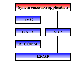
Figure 4: Protocol Stack for Synchronization
8.5.3 Three-in-One Phone
Telephone handsets built
to this profile may connect to three different service providers. First,
telephones may act as cordless phones connecting to the public switched
telephone network (PSTN) at home or the office and incurring a fixed line
charge. This scenario [28] includes making calls via a voice base station,
making direct calls between two terminals via the base station and accessing
supplementary services provided by an external network. Second, telephones can
connect directly to other telephones for the purpose of acting as a
“walkie-talkie” or handset extension. Referred to as the intercom scenario
[29], the connection incurs no additional charge. Third, the telephone may act
as a cellular phone connecting to the cellular infrastructure and incurring
cellular charges. The cordless and intercom scenarios use the same protocol
stack, which is shown in Figure 5. The audio stream is directly connected to
the Baseband protocol indicated by the L2CAP bypassing audio arrow.
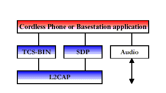
Figure 5 Protocol Stack for Cordless Phone and Intercom Scenarios
8.5.4 Ultimate Headset
The headset can be wirelessly connected for the purpose of acting as a remote device’s audio input and output interface. The headset increases the user’s freedom of movement while maintaining call privacy. A common example is a scenario where a headset is used with either a cellular handset, cordless handset, or personal computer for audio input and output. The protocol stack for this usage model is depicted in Figure 6 [9]. The audio stream is directly connected to the Baseband protocol indicated by the L2CAP bypassing audio arrow. The headset must be able to send AT-commands (Attention commands) and receive result codes. This ability allows the headset to answer incoming calls and then terminate them without physically manipulating the telephone handset.
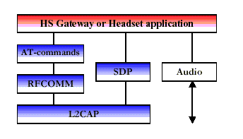
Figure 6 Ultimate Headset Protocol Stack
8.6
Summary
The Bluetooth Protocol Architecture has been developed by the Bluetooth
Special Interest Group (SIG) are intended for rapidly developing applications
using Bluetooth technology. The lower
layers of the Bluetooth stack are designed to provide a flexible base for
further protocol development. RFCOMM
protocols are adopted from existing protocols and these protocols and have been
only slightly modified for the purpose of Bluetooth. The upper layer protocols are used without modifications this has
been to allow existing applications to be reused to work with the Bluetooth
technology and the interoperability is ensured more easily.
9. Connection Establishment in Bluetooth
This section describes the basic procedures to be followed by two or
more Bluetooth devices to start a connection between themselves [31]. Consider
the following scenario: A person walks in to a hotel lobby and wants to access
her email over her Bluetooth enabled device, which could be a laptop or a
Personal Digital Assistant. What would she have to do? Depending on the
implementation., she would be clicking on a menu or an email application icon.
The device would automatically carry out the following steps, (except perhaps
for the authentication step if the device has come to the environment for the
first time):
- Inquiry: The device on reaching a new environment would automatically initiated an inquiry to find out what access points are within its range. (If not, it'll do so when the email application asks for a link.) This will result in the following events:
- All nearby access points respond with their addresses.
- The device picks one out the responding devices.
- Paging: The device will invoke a baseband procedure called paging. This results in synchronization of the device with the access point, in terms of its clock offset and phase in the frequency hop, among other required initializations.
- Link establishment: The LMP will now establish a link with the access point. As the application in this case is email, an ACL link will be used. Various setup steps will be carried out as described below.
- Service Discovery: The LMP will use the SDP (Service Discovery Protocol) to discover what services are available from the access point, in particular whether email access or access to the relevant host is possible from this access point or not. Let us assume that the service is available, otherwise, the application cannot proceed further. The information regarding the other services offered at the access point may be presented to the user.
- L2CAP channel: With information obtained from SDP, the device will create an L2CAP channel to the access point. This may be directly used by the application or another protocol like RFCOMM may be run over it.
- RFCOMM channel: Depending on the need of the email application an RFCOMM or other channel (in case of other applications) will be created over the L2CAP channel. This feature allows existing applications developed for serial ports to run without modification over Bluetooth platforms.
- Security: If the access point restricts its access to a particular set of users or otherwise offers secure mode communications to people having some prior registration with it, then at this stage, the access point will send a security request for "pairing". This will be successful if the user knows the correct PIN code to access the service. Note that the PIN is not transmitted over the wireless channel but another key generated from it is used, so that the PIN is difficult to compromise. Encryption will be invoked if secure mode is used.
- PPP: If a PPP link is used over serial modem as in dial up networking, the same application will now be able to run PPP over RFCOMM (which emulates the serial port). This link will allow the user to login to his email account.
- Network Protocols: The network protocols like TCP/IP, IPX , Appletalk can now send and receive data over the link.
In the above
procedure, user interaction is required only at the usual login for his email
and additionally for the security to be implemented. The remaining steps are
automatic.
10. Bluetooth Security
Bluetooth has powerful security features with the SAFER+(Secure And Fast Encryption Routine) encryption engine using up to 128 bit keys [31].At the Link Level, it is possible to authenticate a device. This verifies that a pair of devices share a secret key derived from a Bluetooth passkey, also known as a Personal Identification Number (PIN). The Bluetooth passkey is entered either in a user interface or for devices such as headsets, which do not have a user interface, the manufacturer can build it in.
After authentication, devices can create shared link keys, which can be used to encrypt traffic on a link. The combination of authentication and creating link keys is calling pairing, possibly accompanied by exchange of higher-level security information, and is called bonding.
Authentication may be repeated after pairing, in which case the link key is used as the shared secret key.
Three modes of security can be implemented: Mode 1 is not secure, Mode 2 has security imposed at the request of applications and services, and Mode 3 has security imposed when any new connection is established.
11. Bluetooth vs. the World
Bluetooth is emerging as the preferred
wireless technology for WPAN [32]. The only other competing technology is
Infrared Technology, known as IrDA. IrDA is the most economical wireless
connectivity solution to implement. In spite of an installed base of over 100
million units worldwide, a series of limitations greatly reduces its potential.
Although operating at a transfer rate of 4 Mbps, greater than that of
Bluetooth, IrDA requires line-of-sight between appliances which significant
reduces usability, its short operating range of 1 meter is a major limitation
that will allow Bluetooth to eventually replace it.
Given the fact that IrDA will enjoy a significant edge over Bluetooth
in terms of installed base, IrDA will likely continue to be integrated into
notebook computers and other handheld devices. As the installed base for
Bluetooth grows the need for IrDA will likely decrease; however, this is not
expected for several years. For the near to medium term IrDA and Bluetooth will
likely coexist.
12. Wireless LAN and 802.11
A wireless LAN (WLAN) is a data transmission system designed to provide
location-independent network access between computing devices by using radio
waves rather than a cable infrastructure [33]. In the corporate enterprise,
wireless LANs are usually implemented as the final link between the existing
wired network and a group of client computers, giving these users wireless
access to the full resources and services of the corporate network across a
building or campus setting.
The widespread acceptance of WLANs depends on industry standardization
to ensure product compatibility and reliability among the various
manufacturers.
The 802.11 specification [35] as a standard for wireless LANS was
ratified by the Institute of Electrical and Electronics Engineers (IEEE) in the
year 1997. This version of 802.11 provides for 1 Mbps and 2 Mbps data rates and
a set of fundamental signaling methods and other services. Like all IEEE 802
standards, the 802.11 standards focus on the bottom two levels the ISO model,
the physical layer and link layer (Figure 7). Any LAN application, network
operating system, protocol, including TCP/IP and Novell NetWare, will run on an
802.11-compliant WLAN as easily as they run over Ethernet.
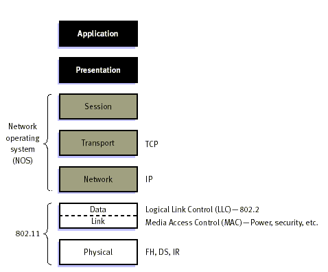
Figure 7: 802.11 and the ISO Model
13. Motivation for WLAN
The major
motivation and benefit from wireless LANs is increased mobility. Untethered
from conventional network connections, network users can move about almost
without restriction and access LANs from nearly anywhere.
The other advantages for WLAN include cost-effective network setup for
hard-to-wire locations such as older buildings and solid-wall structures and
reduced cost of ownership-particularly in dynamic environments requiring
frequent modifications –thanks to minimal wiring and installation costs per
device and user. WLANs
liberate users from dependence on hard-wired access to the network backbone,
giving them anytime, anywhere network access. This freedom to roam
offers numerous user benefits for a variety of work environments, such as:
• Immediate bedside access to patient information for doctors and
hospital staff
• Easy, real-time network access for on-site consultants or auditors
• Improved database access for roving supervisors such as production
line managers, warehouse
auditors, or construction
engineers
• Simplified network configuration with minimal MIS involvement for
temporary setups such as trade shows or conference rooms
• Faster access to customer information for service vendors and
retailers, resulting in better service and
improved customer
satisfaction
• Location-independent access for network administrators, for easier
on-site troubleshooting and support
• Real-time access to study group meetings and research links for
students
14. The 802.11 Architecture
Each computer,
mobile, portable or fixed, is referred to as a station in 802.11 [34]. The
difference between a portable and mobile station is that a portable station
moves from point to point but is only used at a fixed point. Mobile stations
access the LAN during movement. When two or more stations come together to
communicate with each other, they form a Basic Service Set (BSS). The minimum
BSS consists of two stations. 802.11 LANs use the BSS as the standard building
block.
A BSS that stands
alone and is not connected to a base is called an Independent Basic Service Set
(IBSS) or is referred to as an Ad-Hoc Network. An ad-hoc network is a network
where stations communicate only peer to peer. There is no base and no one gives
permission to talk. Mostly these networks are spontaneous and can be set up
rapidly. Ad-Hoc or IBSS networks are characteristically limited both temporally
and spatially.
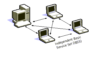
Figure 8: Adhoc Mode
When BSS's are
interconnected the network becomes one with infrastructure. 802.11
infrastructure has several elements. Two or more BSS's are interconnected using
a Distribution System or DS. This concept of DS increases network coverage.
Each BSS becomes a component of an extended, larger network. Entry to the DS is
accomplished with the use of Access Points (AP). An access point is a station,
thus addressable. So, data moves between the BSS and the DS with the help of
these access points.
Creating large
and complex networks using BSS's and DS's leads us to the next level of
hierarchy, the Extended Service Set or ESS. The beauty of the ESS is the entire
network looks like an independent basic service set to the Logical Link Control
layer (LLC). This means that stations within the ESS can communicate or even
move between BSS's transparently to the LLC.
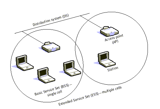
Figure 9: Infrastructure Mode
One of the
requirements of IEEE 802.11 is that it can be used with existing wired
networks. 802.11 solved this challenge with the use of a Portal. A portal is
the logical integration between wired LANs and 802.11. It also can serve as the
access point to the DS. All data going to an 802.11 LAN from an 802.X LAN must
pass through a portal. It thus functions as bridge between wired and wireless.
The
implementation of the DS is not specified by 802.11. Therefore, a distribution
system may be created from existing or new technologies. A point-to-point
bridge connecting LANs in two separate buildings could become a DS.
While the implementation for the DS is not specified, 802.11 does
specify the services, which the DS must support. Services are divided into two
sections
- Station Services (SS)
- Distribution System Services (DSS).
There are five
services provided by the DSS
- Association
- Reassociation,
- Disassociation
- Distribution
- Integration.
The first three services deal with station mobility. If a station is
moving within its own BSS or is not moving, the stations mobility is termed
No-transition. If a station moves between BSS's within the same ESS, its
mobility is termed BSS-transition. If the station moves between BSS's of
differing ESS's it is ESS transition. A station must affiliate itself with the
BSS infrastructure if it wants to use the LAN. This is done by Associating
itself with an access point. Associations are dynamic in nature because
stations move, turn on or turn off. A station can only be associated with one
AP. This ensures that the DS always knows where the station is.
Association supports no-transition mobility but is not enough to
support BSS-transition. Enter Reassociation. This service allows the station to
switch its association from one AP to another. Both association and
reassociation are initiated by the station. Disassociation is when the association
between the station and the AP is terminated. This can be initiated by either
party. A disassociated station cannot send or receive data. ESS-transition are
not supported. A station can move to a new ESS but will have to reinitiate
connections. Distribution and Integration are the remaining DSS's. Distribution
is simply getting the data from the sender to the intended receiver. The
message is sent to the local AP (input AP), then distributed through the DS to
the AP (output AP) that the recipient is associated with. If the sender and
receiver are in the same BSS, the input and out AP's are the same. So the
distribution service is logically invoked whether the data is going through the
DS or not. Integration is when the output AP is a portal. Thus, 802.x LANs are
integrated into the 802.11 DS.
Station services
are:
- Authentication
- Deauthentication
- Privacy
- MAC Service Data Unit (MSDU) Delivery.
With a wireless system, the medium is not exactly bounded as with a
wired system. In order to control access to the network, stations must first
establish their identity. This is much like trying to enter a radio net in the
military.
Before you are acknowledged and allowed to converse, you must first
pass a series of tests to ensure that you are who you say you are. That is
really all authentication is. Once a station has been authenticated, it may
then associate itself. The authentication relationship may be between two
stations inside an IBSS or to the AP of the BSS. Authentication outside of the
BSS does not take place.
There are two types of authentication services offered by 802.11. The
first is Open System Authentication. This means that anyone who attempts to
authenticate will receive authentication. The second type is Shared Key
Authentication. In order to become authenticated the users must be in
possession of a shared secret. The shared secret is implemented with the use of
the Wired Equivalent Privacy (WEP) privacy algorithm. The shared secret is
delivered to all stations ahead of time in some secure method (such as someone
walking around and loading the secret onto each station).
Deauthentication is when either the station or AP wishes to terminate a
stations authentication. When this happens the station is automatically
disassociated. Privacy is an encryption algorithm, which is used so that other
802.11 users cannot eavesdrop on your LAN traffic. IEEE 802.11 specifies Wired
Equivalent Privacy (WEP) as an optional algorithm to satisfy privacy. If WEP is
not used then stations are "in the clear" or "in the red",
meaning that their traffic is not encrypted. Data transmitted in the clear are
called plaintext. Data transmissions, which are encrypted, are called
ciphertext. All stations start "in the red" until they are authenticated.
MSDU delivery ensures that the information in the MAC service data unit is
delivered between the medium access control service access points.
The bottom line is this, authentication is basically a network wide
password. Privacy is whether or not encryption is used. Wired
Equivalent Privacy is used to protect authorized stations from eavesdroppers.
WEP is reasonably strong. The algorithm can be broken in time. The relationship
between breaking the algorithm is directly related to the length of time that a
key is in use. So, WEP allows for changing of the key to prevent brute force
attack of the algorithm. WEP can be implemented in hardware or in software. One
reason that WEP is optional is because encryption may not be exported from the
United States. This allows 802.11 to be a standard outside the U.S. albeit
without the encryption.
14.1
The 802.11 Physical Layer
The three physical layers originally defined in 802.11 included two
spread-spectrum radio techniques and a diffuse infrared specification [33]. The
radio-based standards operate within the 2.4 GHz ISM band. These frequency
bands are recognized by international regulatory agencies radio operations. As such, 802.11-based products do not require user
licensing or special training. Spread-spectrum techniques, in addition to
satisfying regulatory requirements, increase reliability, boost throughput, and
allow many unrelated products to share the spectrum without explicit
cooperation and with minimal interference.
The original 802.11 wireless standard defines data rates of 1 Mbps and
2 Mbps via radio waves using frequency hopping spread spectrum (FHSS) or direct
sequence spread spectrum (DSSS). It is important to note that FHSS and DSSS are
fundamentally different signaling mechanisms and will not interoperate
with one another. Using the frequency hopping technique, the 2.4 GHz
band is divided into 75 1-MHz
subchannels. The sender and receiver agree on a hopping pattern, and
data is sent over a sequence of the subchannels. Each conversation within the
802.11 network occurs over a different hopping pattern, and the patterns are
designed to minimize the chance of two senders using the same subchannel
simultaneously.
FHSS techniques allow for a relatively simple radio design, but are
limited to speeds of no higher than 2 Mbps. This limitation is driven primarily
by FCC (Federal
Communications Commission
USA) regulations that restrict subchannel
bandwidth to 1 MHz. These regulations force FHSS systems to spread their usage
across the entire 2.4 GHz band, meaning they must hop often, which leads to a
high amount of hopping overhead. In contrast, the direct sequence signaling
technique divides the 2.4 GHz band into 14 22-MHz channels. Adjacent channels
overlap one another partially, with three of the 14 being completely non-overlapping.
Data is sent across one of these 22 MHz channels without hopping to other
channels. To compensate for noise on a given channel, a technique called
“chipping” is used. Each bit of user data is converted into a series of
redundant bit patterns called “chips.” The inherent redundancy of each chip
combined with spreading the signal across the 22 MHz channel provides for a
form of error checking and correction; even if part of the signal is damaged,
it can still be recovered in many cases, minimizing the need for
retransmissions.
14.2
The 802.11 Data Link Layer
The data link layer within 802.11 consists of two sublayers [33]:
Logical Link Control (LLC)
and Media Access Control (MAC). 802.11 uses the same 802.2 LLC and
48-bit addressing as other 802 LANs, allowing for very simple bridging from
wireless to IEEE wired networks, but the MAC is unique to WLANs.
The 802.11 MAC is very similar in concept to 802.3, in that it is
designed to support multiple users on a shared medium by having the sender sense
the medium before accessing it. For 802.3 Ethernet LANs, the Carrier Sense
Multiple Access with Collision Detection (CSMA/CD) protocol regulates how
Ethernet stations establish access to the wire and how they detect and handle
collisions that occur when two or more devices try to simultaneously
communicate over the LAN. In an 802.11 WLAN, collision detection is not
possible due to what is known as the “near/far” problem: to detect a collision,
a station must be able to transmit and listen at the same time, but in radio
systems the transmission drowns out the ability of the station to “hear” a
collision. To account for this difference, 802.11 uses a slightly modified
protocol known as Carrier Sense Multiple Access with Collision Avoidance
(CSMA/CA) or the Distributed Coordination Function (DCF). CSMA/CA attempts to
avoid collisions by using explicit
packet acknowledgment (ACK), which means an ACK packet is sent by the
receiving station to confirm that the data packet arrived intact.
CSMA/CA works as follows. A station wishing to transmit senses the air,
and, if no activity is detected, the station waits an additional, randomly
selected period of time and then transmits if the medium is still free. If the
packet is received intact, the receiving station issues an ACK frame that, once
successfully received by the sender, completes the process. If the ACK frame is
not detected by the sending station, either because the original data packet
was not received intact or the ACK was not received intact, a collision is
assumed to have occurred and the data packet is transmitted again after waiting
another random amount of time. CSMA/CA thus provides a way of sharing access
over the air. This explicit ACK mechanism also handles interference and other
radio related problems very effectively. However, it does add some overhead to
802.11 that 802.3 does not have, so that an 802.11 LAN will always have slower
performance than an equivalent Ethernet LAN.
Another MAC-layer problem specific to wireless is the “hidden node” issue,
in which two stations on opposite sides of an access point can both “hear”
activity from an access point, but not from each other, usually due to distance
or an obstruction.
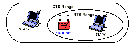
Figure 10: RTS/CTS Procedure eliminates the “Hidden
Node” Problem
To solve this problem, 802.11 specifies an optional Request to
Send/Clear to Send (RTS/CTS) protocol at the MAC layer. When this feature is in
use, a sending station transmits an RTS and waits for the access point to reply
with a CTS. Since all stations in the network can hear the access point, the
CTS causes them to delay any intended transmissions, allowing the sending
station to transmit and receive a packet acknowledgment without any chance of
collision.
Since RTS/CTS adds additional overhead to the network by temporarily
reserving the medium, it is typically used only on the largest-sized packets,
for which retransmission would be expensive from a bandwidth standpoint.
Finally, the 802.11 MAC layer provides for two other robustness
features: CRC checksum and packet fragmentation. Each packet has a CRC checksum
calculated and attached to ensure that the data was not corrupted in transit.
This is different from Ethernet, where higher-level protocols such as TCP
handle error checking. Packet fragmentation allows large packets to be broken
into smaller units when sent over the air, which is useful in very congested
environments or when interference is a factor, since larger packets have a
better chance of being corrupted. This technique reduces the need for retransmission
in many cases and thus improves overall wireless network performance. The MAC
layer is responsible for reassembling fragments received, rendering the process
transparent to higher level protocols.
14.2.1 Support for Time-Bounded Data
Time-bounded data such as voice and video is supported in the 802.11
MAC specification through the Point
Coordination Function (PCF). As opposed to the DCF, where control is
distributed to all stations, in PCF mode a single access point controls access
to the media. If a BSS is set up with PCF enabled, time is spliced between the
system being in PCF mode and in DCF (CSMA/CA) mode. During the periods when the
system is in PCF mode, the access point will poll each station for data, and
after a given time move on to the next station. No station is allowed to
transmit unless it is polled, and stations receive data from the access point
only when they are polled. Since PCF gives every station a turn to transmit in
a predetermined fashion, a maximum latency is guaranteed. A downside to PCF is
that it is not particularly scalable, in that a single point needs to have
control of media access and must poll all stations, which can be ineffective in
large networks.
15. Security in 802.11
Security is one of the first concerns of
people deploying a Wireless LAN, the 802.11 committee has addressed the issue
by providing what is called WEP (Wired Equivalent Privacy)[36].
The main concerns of users are that an intruder would not be able to:
·
Access
the Network resources by using similar Wireless LAN equipment, and
·
Be
able to capture the Wireless LAN traffic (eavesdropping)
15.1
Preventing Access to Network Resources
This is done by the use of an Authentication mechanism where a station
needs to prove knowledge of the current key; this is very similar to the Wired
LAN privacy, on the sense that an intruder needs to enter the premises (by
using a physical key) in order to connect his workstation to the wired LAN.
15.2
Eavesdropping
Eavesdropping is prevented by the use of the WEP algorithm, which is a
Pseude Randon Number Generator (PRNG), initialized by a shared secret key. This
PRNG outputs a key sequence of pseude-random bits equal in length to the
largest possible packet, which is combined with the outgoing/incoming packet
producing the packet transmitted in the air.
The WEP algorithm is a simple algorithm based on RSA’s RC4 algorithm,
which has the following properties:
- Reasonable strong:
Brute-force attack to this algorithm is difficult because of the fact that every frame is sent with an Initialization Vector, which restarts the PRNG for each frame.
- Self Synchronizing:
The algorithm synchronized
again for each message, this is needed in order to work on a connectionless
environment, where packets may get lost (as any LAN).
16. Different 802.11 Standards, 802.11a, 802.11b and 802.11g
The most critical issue affecting WLAN demand has been limited
throughput. The data rates supported by the original 802.11 standard are too
slow to support most general business requirements and slowed the adoption of
WLANs. Recognizing the critical need to support higher data-transmission rates,
the
IEEE ratified the 802.11b standard (also known as 802.11 High Rate) for
transmissions of up to 11 Mbps. After 802.11b one more standard 802.11a has
been ratified and in January 2002 the draft specification of another 802.11g
has been approved. 802.11g is expected to be ratified till early 2003.
The letters after the number "802.11" tell us the order in which the standards were first proposed [37]. This means that the "new" 802.11a is actually older than the currently used 802.11b, which just happened to be ready first because it was based on relatively simple technology-Direct Sequence Spread Spectrum (DSSS), as opposed to 802.11a's Orthogonal Frequency Division Multiplexing (OFDM). The more complex technology provides a higher data rate: 802.11b can reach 11Mbits/sec, while 802.11a can reach 54Mbits/sec.
16.1 802.11b
With 802.11b WLANs, mobile users can get Ethernet levels of
performance, throughput, and availability. The basic architecture, features,
and services of 802.11b are defined by the original 802.11 standard. The
802.11b specification affects only the physical layer, adding higher data rates
and more robust connectivity [33].
The key contribution of the 802.11b addition to the wireless LAN
standard was to standardize the physical layer support of two new speeds,5.5
Mbps and 11 Mbps. To accomplish this, DSSS had to be selected as the sole
physical layer technique for the standard since, as frequency hopping cannot
support
the higher speeds without violating current FCC regulations. The
implication is that 802.11b systems will interoperate with 1 Mbps and 2 Mbps
802.11 DSSS systems, but will not work with 1 Mbps and 2 Mbps 802.11 FHSS systems.
The original 802.11 DSSS standard specifies an 11-bit chipping—called a
Barker sequence—to encode all
data sent over the air. Each 11-chip sequence represents a single data bit (1
or 0), and is converted to a waveform, called a symbol, that can be sent over the air. These symbols are
transmitted at a 1 MSps (1
million symbols per second) symbol
rate using technique called Binary
Phase Shift Keying BPSK). In the case of 2 Mbps, a more
sophisticated implementation called Quadrature
Phase Shift Keying (QPSK) is used; it doubles the data rate
available in BPSK, via improved efficiency in the use of the radio bandwidth.
To increase the data rate in the 802.11b standard, advanced coding techniques
are employed.
Rather than the two 11-bit Barker sequences, 802.11b specifies Complementary Code Keying (CCK), which
consists of a set of 64 8-bit code words. As a set, these code words have
unique mathematical properties that allow them to be correctly distinguished
from one another by a receiver even in the
presence of substantial noise and multipath interference (e.g.,
interference caused by receiving multiple radio reflections within a building).
The 5.5 Mbps rate uses CCK to encode 4 bits per carrier, while the 11 Mbps rate
encodes 8 bits per carrier. Both speeds use QPSK as the modulation technique
and signal
at 1.375 MSps. This is how the higher data rates are obtained. To
support very noisy environments as
well as extended range, 802.11b WLANs use dynamic rate shifting, allowing data rates to be
automatically adjusted to compensate for the changing nature of the radio
channel. Ideally, users connect at the full 11 Mbps rate. However when devices
move beyond the optimal range for 11 Mbps operation, or if substantial
interference is present, 802.11b devices will transmit at lower speeds, falling
back to 5.5, 2, and 1 Mbps. Likewise, if the device moves back within the range
of a higher-speed transmission,
the connection will automatically speed up again. Rate shifting is a
physical layer mechanism transparent to the user and the upper layers of the
protocol stack.
One of the more significant disadvantages of 802.11b is that the frequency band is crowded, and subject to interference from other networking technologies, microwave ovens, 2.4GHz cordless phones (a huge market), and Bluetooth [38]. There are drawbacks to 802.11b, including lack of interoperability with voice devices, and no QoS provisions for multimedia content. Interference and other limitations aside, 802.11b is the clear leader in business and institutional wireless networking and is gaining share for home applications as well.
16.2
802.11a
802.11a, is much faster than
802.11b, with a 54Mbps maximum data rate operates in the 5GHz frequency range
and allows eight simultaneous channels [37]. 802.11a uses Orthogonal
Frequency Division Multiplexing (OFDM), a new encoding scheme that offers
benefits over spread spectrum in channel availability and data rate. Channel
availability is significant because the more independent channels that are
available, the more scalable the wireless network becomes. 802.11a uses OFDM to
define a total of 8 non-overlapping 20 MHz channels across the 2 lower bands.
By comparison, 802.11b uses 3 non-overlapping channels.
All wireless LANs use unlicensed spectrum; therefore
they're prone to interference and transmission errors. To reduce errors, both
types of 802.11 automatically reduce the Physical layer data rate. IEEE 802.11b
has three lower data rates (5.5, 2, and 1Mbit/sec), and 802.11a has seven (48,
36, 24, 18, 12, 9, and 6Mbits/sec). Higher (and more) data rates aren't
802.11a's only advantage. It also uses a higher frequency band, 5GHz, which is
both wider and less crowded than the 2.4GHz band that 802.11b shares with
cordless phones, microwave ovens, and Bluetooth devices.
The wider band means that more radio channels can
coexist without interference. Each radio channel corresponds to a separate
network, or a switched segment on the same network. One big disadvantage is that it is not
directly compatible with 802.11b, and requires new bridging products that can
support both types of networks. Other clear disadvantages are that 802.11a is
only available in half the bandwidth in Japan (for a maximum of four channels),
and it isn't approved for use in Europe, where HiperLAN2 is the standard.
16.3
802.11g
Though 5GHz has many advantages, it also has problems. The most important of these is compatibility: The different frequencies mean that 802.11a products aren't interoperable with the 802.11b base. To get around this, the IEEE developed 802.11g, which should extend the speed and range of 802.11b so that it's fully compatible with the older systems.
The standard operates entirely in the 2.4GHz
frequency, but uses a minimum of two modes (both mandatory) with two optional
modes [38]. The mandatory modulation/access modes are the same CCK
(Complementary Code Keying) mode used by 802.11b (hence the compatibility) and
the OFDM (Orthogonal Frequency Division Multiplexing) mode used by 802.11a (but
in this case in the 2.4GHz frequency band). The mandatory CCK mode supports
11Mbps and the OFDM mode has a maximum of 54Mbps. There are also two modes that
use different methods to attain a 22Mbps data rate--PBCC-22 (Packet Binary
Convolutional Coding, rated for 6 to 54Mbps) and CCK-OFDM mode (with a rated max of 33Mbps).
The obvious advantage of 802.11g is that it
maintains compatibility with 802.11b (and 802.11b's worldwide acceptance) and
also offers faster data rates comparable with 802.11a. The number of channels
available, however, is not increased, since channels are a function of
bandwidth, not radio signal modulation - and on that score, 802.11a wins with
its eight channels, compared to the three channels available with either
802.11b or 802.11g. Another disadvantage of 802.11g is that it also
works in the 2.4 GHz band and so due to interference it will never be as fast
as 802.11a
17. Competing technologies to 802.11
17.1
HiperLAN2
HiperLAN2 is a wireless LAN technology
operating in the license free 5 GHz (5.4 to 5.7 GHz) U-NII band [39]. Under
development by the European Telecommunications Standardization Institute (ETSI)
Broadband Radio Access Networks (BRAN) project, HiperLAN2 is designed to carry
ATM cells, IP packets, firewire packets, and digital data from cellular phones.
Whereas 802.11a is a form of wireless Ethernet, HiperLAN2 is commonly regarded
as wireless ATM.
An extension the 802.11 standard,
802.11a is connectionless Ethernet-like standard, meaning there isn’t a
persistent connection between client and server. On the other hand, HiperLAN2
is based on connection-oriented links, though it can accept Ethernet frames.
802.11a is optimized for data communications, as are all standards based on
802.11.
HiperLAN2 is best suited to wireless
multimedia because of its integrated Quality of Service (QoS) support.
HiperLAN2 will have a difficult time competing with the momentum of 802.11a for
several reasons. 802.11a has year head start over HiperLAN2. In addition, the
802.11a group looking for ways to incorporate the best features of HiperLAN2
within its own standards. It is expected that one merged
European standard will emerge and it
will most likely be 802.11a incorporating the best features of HiperLAN2.
17.2
HomeRF
HomeRF was the first practical wireless home networking technology
and came out in mid-2000 [40]. HomeRF stands for Home Radio Frequency, as it
uses radio frequencies to transmit data over ranges of 75 to 125 feet.
HomeRF uses SWAP (Shared Wireless Access Protocol), which is a
hybrid standard, developed from IEEE 802.11. SWAP can connect up to 127 network
devices and transmits at speeds up to 2Mbps.
Overall the major disadvantage to a HomeRF network is data transmission speed. Two Mbps is fine for sharing files and printing normal files. It is insufficient for streaming media and printing or transferring large graphic files. HomeRF still provides some advantages to those wanting a less expensive wired network solution. HomeRF also does not interfere with Bluetooth and is better for transmitting voice signals.
The following table summarizes the major WLAN standards [41]:
Table 4: Wireless Local Area Networking Technologies
Application
|
Key Technologies
|
Dataspeeds
(Max/Average) |
Date of Introduction
|
The Good
|
The Bad
|
The Bottom Line
|
Enterprise
Networking
|
802.11
|
2 Mbps/ 1.2 Mbps |
Already in use |
Wireless local
area networking |
Slow, expensive,
poor security |
Good start but now
superceded |
|
|
802.11b
|
11 Mbps/5.5 Mbps |
Already in use |
Faster, cheaper,
stronger than 802.11 |
Security still not
cast iron, more expensive than wireline |
Viable for
widespread enterprise adoption now |
|
|
802.11g
|
22 Mbps |
2002
|
Faster than
802.11b |
Specification not
fixed, competing technologies could divide vendor focus |
Should supersede
802.11b within 18 months |
|
Enterprise and Metropolitan Area Networking |
802.11a
|
54 Mbps/24 Mbps, future iterations being planned to support up to 100 Mbps |
2002
|
Faster than
802.11b and 802.11g |
New modulation
scheme and different
frequency band, unlikely to be backward compatible with 802.11b. No support for voice in initial
specification. Costs not proven, likely to be relatively expensive |
Available 2002,
but wait 12 months for cost reduction |
|
|
HiperLAN/2
|
54 Mbps/24 Mbps |
2002
|
Backed by
"big names," supports connection-oriented services such as voice |
Likely to be
expensive. Direct competitor with 802.11a; likely to be the loser in a
head-to-head competition |
Will struggle
against competition from 802.11a |
|
Home Networking |
HomeRF
|
2 Mbps/1 Mbps; planned future
iterations will support up to 10 Mbps |
Already in use |
Fast,
cost-effective home networking standard |
Unlikely to be
established outside home environment |
Some penetration,
but fails to become mainstream |
18. Conclusion
Bluetooth and 802.11b have the potential to dramatically alter how people use devices to connect and communicate in everyday life. Bluetooth is a low-power, short-range technology for ad hoc cable replacement; it enables people to wirelessly combine devices wherever they bring them.
Conversely, 802.11b is a moderate-range, moderate-speed technology based on Ethernet; it allows people to wirelessly access an organizational network throughout a campus location. Although the technologies share the 2.4 GHz band, have some potentially overlapping applications, and have been pitted against each other in the press, they do not compete and can even been successfully combined for corporate use.
One thing is clear, wireless technologies will continue to evolve and offer organizations and end users higher standard of life by making us more mobile and increasing our ability to interact with each other, removing distance as a barrier. There will be a time when a traveler can sit in any airport or hotel and surf the Web or connect to the home office and work. Users will be able to surf or work in places such as malls, parks, or (with smaller handheld computers) just walking down the street. Internet service providers will install larger wireless networks allowing users to connect from anywhere in the city. All of these things are possible with wireless technology.
One day soon, the network will follow you instead of you following it.
19. References
[1] What is Wireless LAN, White Paper, March
1998,
http://www.proxim.com/learn/library/whitepapers/pdf/whatwlan.pdf
[2] Bluetooth
Protocol Architecture, White Paper, 25
August 1999,
http://redwood.snu.ac.kr/nrl/Nrl/FILE/Bluetooth-wp-1C12000.pdf
[3] Bluetooth Special Interest Group, Baseband Specification
[4] Bluetooth Special Interest Group, LMP Specification
[5] Bluetooth Special Interest Group, L2CAP Specification
[6] Bluetooth Special Interest Group, SDP Specification
[7] Bluetooth Special Interest Group, RFCOMM with TS 07.10
[8] Bluetooth Special Interest Group, Telephony Control Protocol Specification
*References [3] to [8] are available in Bluetooth Core Specification, Version 1.1, 25 February 2001, http://www.bluetooth.com/pdf/Bluetooth_11_Specifications.pdf,
[9] Bluetooth Special Interest Group, Headset Profile
[10] Bluetooth Special Interest Group, Dial-Up Networking Profile
[11] Bluetooth Special Interest Group, Fax Profile
*References [9] to [11] are available in Bluetooth Profile Specification, Version 1.1,
25 February 2001,http://www.bluetooth.com/pdf/Bluetooth_11_Profiles_Book.pdf,
[12] Internet Engineering Task Force, IETF Directory List of RFCs, July 1999,
[13] Bluetooth Special Interest Group, IrDA Interoperability
[14] Bluetooth Special Interest Group, Interoperability Requirements for Bluetooth as a WAP Bearer
*References [13] and [14] are available in Bluetooth Core Specification, Version 1.1, 25 February 2001 http://www.bluetooth.com/pdf/Bluetooth_11_Specifications.pdf.
[15] The Internet Mail Consortium, vCard - The Electronic Business Card Exchange Format, Version 2.1, September 1996, http://www.imc.org/pdi/
[16] The Internet Mail Consortium, vCalendar - The Electronic Calendaring and Scheduling Exchange Format, Version 1.0, September 1996, http://www.imc.org/pdi/
[17] Infrared Data Association, IrMC (Ir Mobile Communications) Specification, Version 1.1, February 1999, http://www.irda.org/standards/pubs/IrMC_v1p1Specs&Errata001024.zip
[18] WAP Forum, WAP Forum Specifications, July 1999
http://www.wapforum.org/what/technical.htm
[19] Bluetooth Special Interest Group, LAN Access Profile using PPP, Bluetooth Profile Specification, Version 1.1, 25 February 2001, http://www.bluetooth.com/pdf/Bluetooth_11_Profiles_Book.pdf
[20] Infrared Data Association, IrDA Object Exchange Protocol (IrOBEX), Version 1.2, April 1999,
http://www.irda.org/standards/pubs/IrOBEX1p2_Plus_Errata.zip
[21] Bluetooth Special Interest Group, Generic Access Profile
[22] Bluetooth Special Interest Group, Serial Port Profile
[23] Bluetooth Special Interest Group, Service Discovery Application Profile
[24] Bluetooth
Special Interest Group, Generic Object Exchange Profile
[25] Bluetooth Special Interest Group, File Transfer Profile
[26] Bluetooth Special Interest Group, Object Push Profile
[27] Bluetooth Special Interest Group, Synchronization Profile
[28] Bluetooth Special Interest Group, Cordless Telephony Profile
[29] Bluetooth Special Interest Group, Intercom Profile
*References [21] to [29] are available in Bluetooth Profile Specification, Version 1.1, 25 February 2001, http://www.bluetooth.com/pdf/Bluetooth_11_Profiles_Book.pdf
[30] Bluetooth Protocol Architecture, White Paper, By Sailesh Rathi, 2000 Q4,
www.realtime-info.be/magazine/00q4/2000q4_p028.pdf
[31] ‘Bluetooth Connect Without Cables’ by
Jennifer Bray and Charles F Sturman
[32] Bluetooth Technology Overview, White
Paper , November 2000,
www.compaq.com/products/wireless/wpan/files/WhitePaper_BluetoothTechnologyOverview-QA.pdf
[33] IEEE 802.11 Wireless LANs, Technical paper, January 2000,
www.3com.com/corpinfo/en_US/technology/tech_paper.jsp?DOC_ID=71
[34] Wireless Local Area Networks, April 2002,
http://www.cis.ohio-state.edu/~jain/cis788-97/wireless_lans/index.htm
[35] IEEE
Std 802.11, 1999 Edition (ISO/IEC
8802-11: 1999) IEEE Standard for Information Technology - Telecommunications
and Information Exchange between Systems - Local and Metropolitan Area Network
- Specific Requirements - Part 11: Wireeless LAN Medium Access Control (MAC) and
Physical Layer (PHY) Specifications,
http://standards.ieee.org/reading/ieee/std/lanman/802.11-1999.pdf
[36] A Technical Tutorial on the IEEE 802.11
Protocol, by Pablo Brenner, July 1996
www.sss-mag.com/pdf/802_11tut.pdf
[37] Emerging Technology:
Wireless Lan Standards, 2 June 2002, http://www.networkmagazine.com/article/NMG20020206S0006/2
[38] Wireless Standards Up in the Air, 21 February 2002,
http://www.extremetech.com/article/0,3396,s=1034&a=19393&app=1&ap=2,00.asp
[39]
802.11a FAQ, November 2001, www.3com.com/corpinfo/en_US/technology/tech_paper.jsp?DOC_ID=161
[40]
HomeRF Frequently Asked Questions, April 2002,
http://www.homerf.org/learning_center/faq.html
[41] Research
Brief Personal to Global:
Wireless Technologies, 23 February 2001,
http://cnscenter.future.co.kr/resource/rsc-center/gartner/95762.pdf