 |
|
|
|
|
|
|
|
|
|
|
|
|
|
|
|
|
|
|
|
|
|
|
|
|
|
|
|
|
|
 |
|
|
|
Baldwin produced the first AS416 for the Savannah and Atlanta on December 6, 1950. The AS416 was an uncomon locomotive because it had a wheel arrangement of A1A-A1A and was a road switcher. Only ten percent of all Baldwin road switchers produced for service in North America had this wheel arrangement. Of the six axles, only four axles were powered. Baldwin did this for two reasons. The first was to complete with Alco who also produced road switchers with an A1A-A1A wheel arrangement. The second reason was to allow railroads to purchase a locomotive that could be run on light weight track or track with severe weight restrictions.
Baldwin produced the DRS-6-4-15 from September 30, 1946 until it was replaced by the AS416 (DRS-6-4-16). Of the 25 1600hp road switchers built, 23 of them had the exact same body configuration as the earlier 1500 hp units, which can be shown in the picture below. |
|
|
|
 |
|
|
|
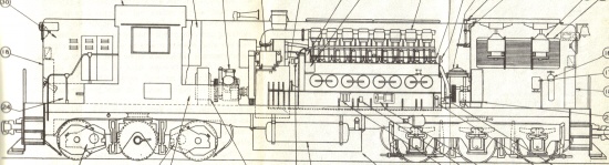
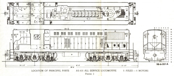
AS416 illustration from operator's manual AS-101-A showing equipment layout generally applicable to all 1500 hp and most 1600 hp A1A-A1A Baldwin units. |
|
|
|
In this body style, a railroad could order one of these locomotives with either a steam generator or dynamic brakes. However, in October of 1949, EMD produced the GP7 that had both a steam generator and dynamic brakes, puting Baldwin at a disadvantage. To answer to EMD's new locomotive, Baldwin redesigned the body so they too could hold both a steam generator and dynamic brakes as shown in the picture below. |
|
|
|
 |
|
|
|
Thhs illustration shows the place for a steam generator at the rear of the locomotive and dynamic brakes at the front of the locomotive, in the radiator compartment
A system of shutters allows the same fans to either cool the radiators or the dynamic brakes. |
|
|
|
|
|
AS416 illustration from operator's manual AS-104, showing the redesigned locomotive body. |
|
|
|
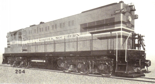
After Savannah and Atlanta ordered the twenty-third AS416 on August 5, 1955, several design changes were made to the model. Only two locomotives were ever built with these changes, one of which is pictured at the top of the page. These two locomotives were built for Norfolk Southern and used over the railroad's 10 mile-long Albemarle Sound trestle, which prohibited other locomotives with higher axle loading.
The major difference between these two AS416's and the previous AS416's was the introduction of General Electric equipment, which included the main generator, the auxiliary-exciter generator, the traction motors, and the control stand. |
|
|
|
 |
|
|
|
Below: AS416 illustration from operator's manual AS-104, showing the new GE 17KC91H control stand. The 17KC91H is an electric throttle that was found in these two locomotives. |
|
|
|
|
|
 |
|
|
|
|
Above: AS416 illustration from operator's manual AS-101-A, showing the typical D-1 control stand for Westinghouse locomotives that do not have dynamic brakes. The D-1 is the simpler of two Westinghouse air operated throttles found on Baldwim locomotives. There was also a Westinghouse electric throttle. |
|
|
|
|
|
|
The illustrations and information about the two Norfolk Southern AS416's comes from an extremely rare operator's manual, the Baldwin-Lima-Hamilton manual number AS-104, which covers AS series locomotives with General Electric equipment. NS no.1616-1617 are the only two units ever built, which are covered by this manual.
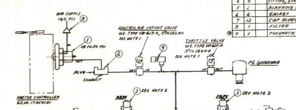
It should be noted that NS 1616-1617 did not have dynamic brakes, although the diagram above shows the design with dynamic brakes. If any locomotives had been built with GE equipment and dynamic brakes, they would have had a mutated controller as shown below. |
|
|
|
 |
|
|
|
Above is a section of a schematic found on page 43 of B-L-H manual AS-104, published 10-1-55 and which covers AS-series locomotives equipped with General Electric equipment. It shows what is described as a "typical pneumatic control system." Number 1 on the diagram is listed as a controlair valve; "controlair" is another Westinghouse term for the D-1 throttle valve. As you can see, the controlair valve has been mounted to the GE master controller, with part number 17KC91H1, which is different from that shown in the cab view above. In the manual, the electric throttle (19KC91H) is described as standard; thus, it is the assumption that NS 1616-1617 did not use the pneumatic arrangement seen here.
The section of this manual covering dynamic braking describes only a pneumatic throttle system. Also, GE equipped units of this time period required a selector lever to select, and to control, dynamic braking -- and the KC91 controller does not have a selector lever. |
|
|
|
 |
|