 |
|
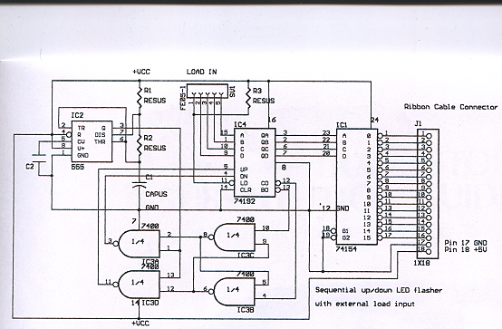
| Sequential UP/DN LED Flasher |
| Circuit Operation: |
| The 555 astable oscillator/timer supplies squarewave pulses to gates IC3A and IC3D, pins 1 and 13 on the 7400IC . IC3C and IC3B form a flip-flop under control of the 74193 up/ down binary counter's carry and borrow output ,pins 12 and 13 respectively. The 74193IC counts the incoming pules and outputs a binary coded digit (via pins 2,3,6.7) to the 74154IC, a 4 to 1 of 16 decoder, which outputs a High corresponding to the binary digit it received (via pins 23,22,21,20) from the 74193. When the 74193 reaches its maximum count (15 or 1111 binary) ,pin 12 outputs a high to pin 4 on IC3B which opens gate IC3A. Pulses then exit pin 3 on IC3A which allows the 74193 to count backwards from 15 to 0 |
| ON UP count LEDs 1 thru 17 will go high(brighten) one at a time in seqence. On Down count LEDs 17 thru 1 will go high in sequence. The flash rate is determined by the values chosen for R1,R2 and C1 on the 555 astable. Typical values are 10k for R1, 50k for R2 and 1UF for C1 but any values can be used. R2 can be substituted with a 100k potentiometer if variabe control is required. |
| The LEDs and power supply would be on a seperate PC board connected via the 18 pin ribbon cable. All LED cathodes are connnected to common ground and each LED anode would connect to pins 1 thru 17 on the 74154IC via the ribbon cable. |
| The LEDs can be substituted with other components such as relays ,opto couplers, transistors,SCRs, or a Memory IC. |