 |
|
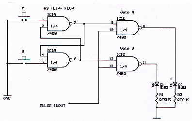
| The Basic RS Flip-Flop Gate |
| Circuit Operation: |
| This is a rather simple circuit but useful. When button A is depressed input pulses exit gate A via pin 8, when button B is depressed input pulses exit gate B. Note that when pulses exit a gate (either A or B) the corresponding LED will flash in time with the pulses. IC1A and IC1B form a flip-flop circuit while IC1C and IC1D form two seperate AND gates. Because of the way flip-flops operate only one gate will be on at a time. The push buttons can be replaced with other compononts, such as a timer which would allow a certain number of input pulses to enter and exit .( a frequency counter maybe ? ) |